Elenco Snap Circuits XP ® User Manual
Page 23
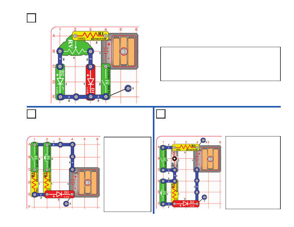
Turn on the circuit using the slide switch (S1) and move the
adjustable resistor’s (RV) control lever around to adjust the
brightness of the LEDs (D1 & D2). When the adjustable resistor
is set to one side, that side will have low resistance and its LED
will be bright (assuming the switch on that side is ON) while the
other LED will be dim or OFF.
Project A19
Parallel Resistors
Project A20
Series Resistors
Project A18
Slider
-22-
Turn on either or both
switches (S1 & S2) and
compare the LED (D1)
brightness.
This circuit has the 100
W
resistor (R1) and 1k
W
resistor (R2) arranged in
parallel. The smaller
100
W
resistor controls the
brightness in this
arrangement.
You can replace either
resistor with any other
resistor and compare the
effect.
Turn on either or both switches
(S1 & S2) and compare the
LED (D1) brightness.
This circuit has the 100
W
resistor (R1), the 1k
W
resistor
(R2), and the photoresistor
(RP) arranged in series. The
switches are used to bypass
the larger resistors. The
largest resistor controls the
brightness in this
arrangement. The resistance
of the photoresistor will be
much higher than the others,
unless the light is very bright.