Minia ture radio transmitter, Circuit opera tion, High freq uency oscilla t o r – Elenco Whooper Alarm User Manual
Page 4: Constr uction, Figure 1 figure 2 figure 3
-4-
-3-
MINIA
TURE RADIO
TRANSMITTER
The
Whooper Alar
m puts out a w
a
v
e
ring sound that is sure to star
tle an
intr
uder
. It can be used independently or as an accessor
y
to the Burglar
Alar
m Kit K-23.
The
Whooper Alar
m circuit consists of tw
o oscillators
, a lo
w frequency
oscillator which dr
iv
es a higher frequency unit at a predeter
mined r
a
te
.
The high frequency oscillator dr
iv
es an output tr
ansistor which po
w
e
rs the
speak
er
.
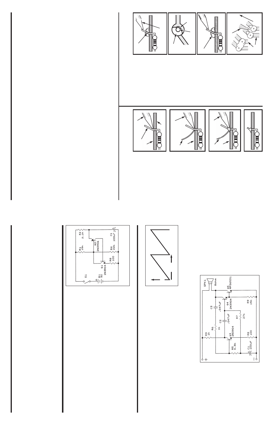
CIRCUIT OPERA
TION
Figure 1 sho
w
s the circuits of the lo
w frequency oscillator
.
When the
po
w
e
r is first applied to this circuit, tr
ansistors Q1 and Q2 will not conduct.
This is because the base of tr
ansistor Q2 is about 5.4V while the emitter
is at z
e
ro v
olts
.
A current is flo
wing in resistor R2 charging capacitor C1.
When the v
oltage
across C1 reaches 6V
, tr
ansistor Q2 star
ts sending a current in the
collector of Q1.
The current in the collector of Q1 is m
ulitplied b
y
the gain
of tr
ansistor Q1 and this r
apidly tur
n
s on tr
ansistor Q2.
Capacitor C1
quic
kly discharges through resistor R8 as sho
wn in Figure 2.
Note that C1
charges through a 2200
Ω
resistor R2, b
u
t discharges through a 100
Ω
resistor R8.
Thus
, the charge to discharge r
a
tio is 22:1.
When C1 is
discharged, Q1 and Q2 tur
n
off and the whole cycle repeats itself
.
HIGH FREQ
UENCY OSCILLA
T
O
R
The circuit of the high frequency oscillator is sho
wn in Figure 3.
T
ransistors Q3 and Q4 are wired as amplifier stages
.
The bias f
o
r these
amplifiers are controlled b
y
the sa
wtooth of Figure 2.
These amplifiers
nor
mally w
ould amplify the lo
w frequency pulses
, e
xcept f
o
r the addition of
capacitor C3.
This capacitor tak
e
s the output of Q4 and f
eeds it in phase
to the input of Q3.
This causes the circuit to oscillate
.
The frequency of
oscillation is controlled b
y
the RC time constants of C3 and R6.
The
frequency of oscillation is about 1,000 cycles per second.
This frequency
is modulated with the lo
w frequency oscillations to produce the
Whooper
Alar
m sounds
.
T
ransistor Q5 fur
ther amplifies the signals and dr
iv
es the
speak
er
.
Figure 1
Figure 2
Figure 3
V
olts
Time
CONSTR
UCTION
Solder
Solder
ing Iron
F
oil
Solder
Solder
ing Iron
F
oil
Component Lead
Solder
ing Iron
Circuit Board
F
oil
Rosin
Solder
ing iron positioned
incorrectly
.
Solder
Gap
Component Lead
Solder
Solder
ing Iron
Dr
ag
F
oil
1.
Solder all components from the
copper f
oil side only
. Push the
solder
ing iron tip against both the
lead and the circuit board f
oil.
2.
Apply a small amount of solder to
the iron tip
. This allo
ws the heat to
lea
v
e
the iron and onto the f
oil.
Immediately apply solder to the
opposite side of the connection,
a
w
a
y
from the iron.
Allo
w the
heated component and the circuit
foil to melt the solder
.
1.
Insufficient heat
- the solder will
not flo
w
onto the lead as sho
wn.
3.
Allo
w the solder to flo
w
around
the connection.
Then, remo
v
e
the solder and the iron and let the
connection cool.
The solder
should ha
v
e
flo
w
ed smoothly and
not lump around the wire lead.
4.
Here is what a good solder
connection looks lik
e
.
2.
Insufficient solder
- let the
solder flo
w
o
v
er the connection
until it is co
v
e
red.
Use just enough solder to co
v
e
r
the connection.
3.
Excessive solder
- could mak
e
connections that y
ou did not
intend to betw
een adjacent f
oil
areas or ter
m
inals
.
4.
Solder bridg
e
s
- occur when
solder r
uns betw
een circuit paths
and creates a shor
t circuit.
This is
usually caused b
y
using too m
u
ch
solder
.
T
o
correct this
, simply dr
ag y
our
solder
ing iron across the solder
br
idge as sho
wn.
What Good Soldering Looks Like
A good solder connection should be br
ight, shin
y,
smooth, and unif
or
mly
flo
w
ed o
v
er all surf
aces
.
T
y
pes of P
oor Soldering Connections
Intr
oduction
The most impor
tant f
a
ctor in assemb
ling y
our K-24
Whooper Alar
m Kit
is good solder
ing techniques
. Using the proper solder
ing iron is of pr
ime
impor
tance
. A small pencil type solder
ing iron of 25 - 40 w
a
tts is
recommended.
The tip of the ir
on m
u
st be kept c
lean at all times and
well tinned.
Solder
F
o
r man
y
y
ears leaded solder w
a
s the most common type of solder
used b
y
the electronics industr
y,
b
u
t it is no
w being replaced b
y
lead-
free solder f
o
r health reasons
.
This kit contains lead-free solder
, which
contains 99.3% tin, 0.7% copper
, and has a rosin-flux core
.
Lead-free solder is diff
e
rent from lead solder
: It has a higher melting
point than lead solder
, so y
ou need higher temper
ature f
o
r the solder to
flo
w
proper
ly
. Recommended tip temper
ature is appro
x
imately 700
O
F;
higher temper
atures impro
v
e solder flo
w
b
u
t acceler
ate tip deca
y.
An
increase in solder
ing time ma
y be required to achie
v
e
good results
.
Solder
ing iron tips w
ear out f
a
ster since lead-free solders are more
corrosiv
e
and the higher solder
ing temper
atures acceler
ate corrosion,
so proper tip care is impor
tant.
The solder joint finish will look slightly
duller with lead-free solders
.
Use these procedures to increase the lif
e of y
our solder
ing iron tip when
using lead-free solder
:
•
K
eep the iron tinned at all times
.
•
U
se the correct tip siz
e
f
o
r best heat tr
ansf
e
r.
The conical tip is the
most commonly used.
•
T
ur
n off iron when not in use or reduce temper
ature setting when
using a solder
ing station.
•
Tips should be cleaned frequently to remo
ve
o
xidation bef
ore it becomes
impossib
le to remo
ve
. Use Dr
y
Tip Cleaner (Elenco
®
#SH-1025) or
Tip
Cleaner (Elenco
®
#TTC1).
If y
ou use a sponge to clean y
our tip
, then use
distilled w
a
ter (tap w
a
ter has impur
ities that acceler
ate corrosion).
Saf
e
ty Pr
ocedures
•
Al
wa
ys wear saf
ety glasses or saf
ety gog
gles to
pr
otect y
our e
y
es when w
orking with tools or
soldering ir
on,
and during all phases of testing.
•
B
e sure there is
adequate ventilation
when solder
ing.
•
Locate solder
ing iron in an area where y
ou do not ha
ve
to go around
it or reach o
ver it.
K
eep it in a saf
e
area a
w
a
y
from the reach of
children.
•
Do not hold solder in y
our mouth.
Solder is a to
xic substance
.
W
a
sh hands thoroughly after handling solder
.
Assemb
le Components
In all of the f
ollo
wing assemb
ly steps
, the components m
u
st be installed
on the top side of the PC board unless otherwise indicated.
The top
legend sho
w
s where each component goes
. The leads pass through the
corresponding holes in the board and are soldered on the f
oil side
.
Use onl
y r
o
sin core solder
.
DO NO
T USE A
C
ID CORE SOLDER!
'