Warning, Assemble components t o the pc bo ard, Identifying resist or v a lues – Elenco Whooper Alarm User Manual
Page 3: Metric units and conversions, Identifying cap a c it or v a lues
-2-
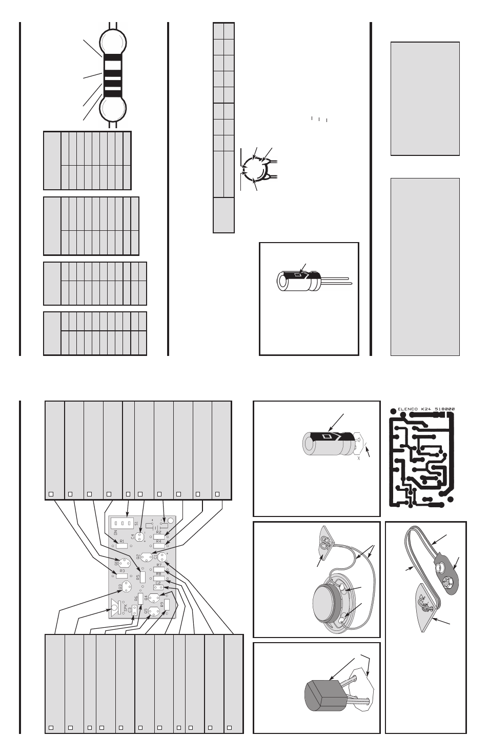
ASSEMBLE COMPONENTS
T
O
THE PC BO
ARD
Figure B
Cut tw
o 4”
wires and str
ip 1/8”
of
insulation off of both wires
. Solder a
wire to each lug of the speak
er and then
inser
t the other end of the wires through
the hole in the PC board, and solder in
the place sho
wn on the top legend.
-5-
Figure A
Mount the tr
ansistor with the
flat side in the same direction
as sho
wn on the PC board.
Solder and cut off the e
xcess
leads
.
Q3 - 2N3904
T
ransistor
(see Figure A)
SPK - Speak
er
(see Figure B)
C3 - .047
μ
F (473) Discap
R6 - 1k
Ω
5% 1/4W Resistor
(bro
wn-b
lac
k-red-gold)
Q5 - MPS 6531
T
ransistor
(see Figure A)
R9 - 15k
Ω
5% 1/4W Resistor
(bro
wn-g
reen-or
ange-gold)
Q4 - 2N3904
T
ransistor
(see Figure A)
C2 - .047
μ
F (473) Discap
R8 - 100
Ω
5% 1/4W Resistor
(bro
wn-b
lac
k-bro
wn-gold)
R7 - 27k
Ω
5% 1/4W Resistor
(red-violet-or
ange-gold)
C1 - 100
μ
F Electrolytic Cap
.
(see Figure C)
R3 - 1k
Ω
5% 1/4W Resistor
(bro
wn-b
lac
k-red-gold)
Q1 - 2N3904
T
ransistor
(see Figure A)
R5 - 6.8k
Ω
5% 1/4W Resistor
(b
lue-g
ra
y
-red-gold)
R1 - 15k
Ω
5% 1/4W Resistor
(bro
wn-g
reen-or
ange-gold)
S1 - Slide Switch
C4 - 100
μ
F Electrolytic Cap
.
(see Figure C)
B1 - Batter
y
Snap
(see Figure D)
R2 - 2.2k
Ω
5% 1/4W Resistor
(red-red-red-gold)
R4 - 22k
Ω
5% 1/4W Resistor
(red-red-or
ange-gold)
Q2 - 2N3906
T
ransistor
(see Figure A)
Foil Side of PC Boar
d
Flat
Figure C
Electrolytic capacitors ha
v
e
polar
ity
. Be
sure to mount them with the negativ
e (–)
lead (mar
k
ed on side) in the correct
hole
.
Figure D
Inser
t the red and b
lac
k wires
through the hole in the PC board
as sho
wn.
Inser
t the red wire into
the positiv
e (+) hole and the b
lac
k
wire into the negativ
e hole
. Solder
and cut off the e
xcess leads
.
P
olar
ity
mar
k
ing
Speak
er lugs
4”
Wires
PC board
Mar
k
ing on legend side of PC board
Blac
k
Red
PC board
Batter
y
snap
IDENTIFYING RESIST
OR
V
A
LUES
Use the f
ollo
wing inf
or
mation as a guide in proper
ly identifying the v
alue of resistors
.
B
ANDS
METRIC UNITS AND CONVERSIONS
Abbre
v
iation
Means
Multipl
y Unit By
Or
p
pico
.000000000001
10
-12
n
nano
.000000001
10
-9
μ
micro
.000001
10
-6
m
m
illi
.001
10
-3
–
unit
1
1
0
0
k
k
ilo
1,000
10
3
M
m
ega
1,000,000
10
6
1.
1,000 pico units
=
1 nano unit
2.
1,000 nano units
=
1 micro unit
3.
1,000 micro units
=
1 milli unit
4.
1,000 milli units
=
1 unit
5.
1,000 units
=
1 kilo unit
6.
1,000 kilo units
=
1 mega unit
IDENTIFYING CAP
A
C
IT
OR
V
A
LUES
Capacitors will be identified b
y
their capacitance v
alue in pF (picof
ar
ads), nF (nanof
ar
ads), or
μ
F (microf
ar
ads).
Most capacitors will ha
v
e
their actual v
alue pr
inted on them.
Some capacitors ma
y ha
v
e
their v
alue pr
inted in
the f
ollo
wing manner
.
The maxim
u
m oper
ating v
oltage ma
y also be pr
inted on the capacitor
.
Second Digit
First Digit
Multiplier
T
oler
ance
*
Note:
The letter
“R”
ma
y be used at times
to signify a decimal
point;
as in 3R3 = 3.3
103K
100V
The letter M indicates a toler
ance of +
20%
The letter K indicates a toler
ance of +
10%
The letter J indicates a toler
ance of +
5%
Maxim
u
m W
o
rk
ing
V
oltage
The v
alue is 10 x 1,000 =
10,000pF or .01
μ
F 100V
*
Electrolytic capacitors ha
v
e
a positiv
e
and a negativ
e electrode
.
The
negativ
e
lead is indicated on the
pac
kaging b
y
a str
ipe with min
u
s
signs and possib
ly arro
wheads
.
W
arning:
If the capacitor
is connected
with incorrect
polarity
, it ma
y
heat up and
either leak,
or
cause the
capacitor to
e
x
plode
.
P
olar
ity
Mar
k
ing
B
AND 1
1st Digit
Color
Digit
Blac
k
0
Bro
w
n
1
Red
2
Or
ange
3
Y
ello
w
4
Green
5
Blue
6
Violet
7
Gr
a
y
8
White
9
B
AND 2
2nd Digit
Color
Digit
Blac
k
0
Bro
w
n
1
Red
2
Or
ange
3
Y
ello
w
4
Green
5
Blue
6
Violet
7
Gr
a
y
8
White
9
Multiplier
Color
Multiplier
Blac
k
1
Bro
w
n
10
Red
100
Or
ange
1,000
Y
ello
w
10,000
Green
100,000
Blue
1,000,000
Silv
er
0.01
Gold
0.1
Resistance
T
olerance
Color
T
olerance
Silv
er
±10%
Gold
±5%
Bro
w
n
±1%
Red
±2%
Or
ange
±3%
Green
±0.5%
Blue
±0.25%
Violet
±0.1%
1
2
M
ultiplier
T
oler
ance
Multiplier
F
o
r the No
.
0
1
2
3
4
5
8
9
Multiply By
1
10
100
1k
10k
100k
.01
0.1
W
arning:
If the capacitor is
connected with
incorrect polarity
, it
ma
y heat up and
either leak,
or cause
the capacitor to
e
x
plode
.