Elenco Burglar Alarm User Manual
Page 4
-3-
When we place a voltage to the gate, a current will
flow between the anode and cathode turning ON
the alarm buzzer. If we remove the voltage on the
gate, the current will continue to flow in the SCR.
Thus, if a burglar opens the door, the alarm will go
off. Closing that door will not turn off the alarm, it will
continue to sound. The only way to turn it off is to
remove the power to the SCR.
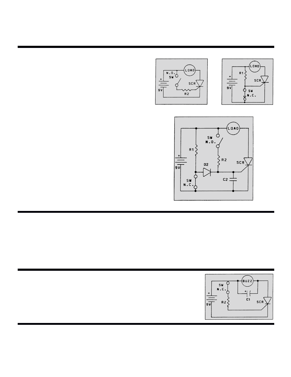
ACTIVATING SWITCHES
There are two types of activating switches, the
normally open (N.O.) contacts and normally closed
(N.C.) contacts. Figure 2A shows the N.O. circuit.
Remember that the SCR needs gate voltage to fire.
When the N.O. switch is closed, the SCR will
conduct current and continue to do so even if the
N.O. switch is opened.
Figure 2B shows the circuit for a N.C. switch. Here,
while the switch is closed, no voltage will be seen at
the gate of the SCR. Once the switch is open, the
SCR will conduct and continue to do so until the
voltage is removed from the anode of the SCR. This
important turn on / no turn off feature prevents the
intruder from turning off the alarm. When we combine
the N.O. and the N.C. circuits, a problem occurs. The
N.C. switch will short out the N.O. switch voltage. To
prevent this, we add a diode to isolate the two
circuits. Figure 3 shows this circuit. The diode D2
prevents the voltage from being shorted out through
the N.C. switch. Voltage from R1 will pass through
the diode and into the gate of the SCR when SW
N.C. is open.
Figure 2A
Figure 2B
Figure 3
When this alarm is used in an automobile, any
jarring of the contact switches may set off the alarm.
To prevent this, a capacitor (C2) is added to the
circuit. Figure 3 shows the location of C2. When the
N.C. or N.O. switch is first activated, the current
through R1 or R2 first goes to charge the capacitor.
After the capacitor is charged, then the voltage will
build up enough to trigger the SCR. The time may
seem very fast, but in electronics, it is a long time
when you consider circuits react in microseconds
(0.000001 sec.). Thus, by adding capacitor C2, any
noise spike shorter than one millisecond will not fire
the alarm.
ELIMINATING FALSE ALARMS
The alarm device used in this circuit is a buzzer.
This device operates by vibrating back and forth,
interrupting the current. Remember that the SCR
will turn off if the gate has no voltage and the anode
also loses its voltage to the anode, a capacitor (C1)
is added across the buzzer, as shown in Figure 4.
This capacitor will
keep the current
flowing in the SCR
whenever the buzzer
opens up.
KEEPING THE ALARM ON
The Burglar Alarm can be used to control a relay,
such as the relay in your auto horn system. To do so,
simply replace the buzzer with the relay. Whenever
the alarm is fired, the relay will close, setting off the
alarm. A diode (D1) is placed across the relay to
remove the excessive voltage generated by the
relay coil from damaging the SCR.
EXTERNAL ALARM
Figure 4