Assemble components to the pc board – Elenco FM Wireless Microphone Kit User Manual
Page 7
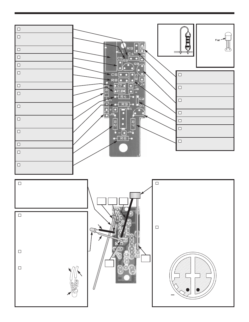
ASSEMBLE COMPONENTS TO THE PC BOARD
-6-
C4 - 10pF Discap (10)
Q2 - 2N3904 Transistor
(see Figure A)
L1 - Coil
C5 - 12pF Discap (12)
C6 - 33pF Discap (33)
R8 - 1k
Ω
5% 1/4W Res.*
(brown-black-red-gold)
C7 - .001
µ
F Discap (102)
R10 - 1k
Ω
5% 1/4W Res.*
(brown-black-red-gold)
R1 - 8.2k
Ω
5% 1/4W Res.
(gray-red-red-gold)
R4 - 47k
Ω
5% 1/4W Res.
(yellow-violet-orange-gold)
R3 - 4.7k
Ω
5% 1/4W Res.
(yellow-violet-red-gold)
C1 - .1
µ
F Discap (104)
R2 - 27k
Ω
5% 1/4W Res.
(red-violet-orange-gold)
R6 - 10k
Ω
5% 1/4W Res.
(brown-black-orange-gold)
R5 - 150
Ω
5% 1/4W Res.*
(brown-green-brown-gold)
R9 - 47k
Ω
5% 1/4W Res.*
(yellow-violet-orange-gold)
Q3 - 2N3904 Transistor
(see Figure A)
C3 - .001
µ
F Discap (102)
C2 - .1
µ
F Discap (104)
Q1 - 2N3904 Transistor
(see Figure A)
R7 - 1.5k
Ω
5% 1/4W Res.
(brown-green-red-gold)
Mount the
transistor
with the
flat side
as shown
on the top
legend.
Figure A
Mount
these
resistors
on end.
*
Top Legend of PC Board
Strip the insulation off of one end
of the 12” gray wire to expose 1/8”
of bare wire. Mount and solder the
wire to the foil side of the PC board
in hole J5.
Cut a 1 1/2” red wire and 1 1/2”
black wire. Strip the insulation off
of both ends to expose 1/8” of bare
wire.
Mount and solder the red
wire to the foil side of the PC board
in hold J6 (+) and the black wire to
hole J7 (–).
Cut the leads of the LED so that
they are 1/4” long, then spread
them slightly apart (see Figure B).
Solder the free end of
the black wire to the
flat side lead of the
LED. Solder the free
end of the red wire to
the other lead of the
LED.
Figure B
If your microphone has leads attached
to it, cut them off flush with the pads on
the microphone. Cut a 2” piece of red
wire and a 2” piece of black wire. Strip
the insulation off of both ends to expose
1/8” of bare wire. Solder the red wire to
the foil side of the PC board in hole J1
(+) and the black wire to hole J2 (–).
Solder the free end of the red wire to
the (+) pad on the mic and the black
wire to the (–) pad on the mic as shown
in Figure C.
Figure C
+
J7
J2
J1
J6
J5
Black
Red
Foil Side of PC Board
Red
Black
Flat