Project #pc35 adjustable tone generator pc (ii), Project #pc38 adjustable fm radio pc – Elenco Projects PC1-PC73 User Manual
Page 45
-44-
Try these settings to
see the spectrum:
Modify the circuit for project PC34 by placing the 0.02
m
F capacitor
(C1) on top of the whistle chip (WC). Look at the waveform and
frequency spectrum using the same settings as for project PC34,
the frequency is lower now.
Project #PC35
Adjustable Tone Generator PC (II)
Modify the circuit for project PC34 by
placing the 0.1
m
F capacitor (C2) on top of
the whistle chip (WC).
Look at the
waveform and frequency spectrum using
the same settings as for project PC34, but
you may want to change the time scale
since the frequency is much lower now.
Project #PC36
Adjustable Tone Generator PC (III)
Project #PC37
Adjustable Tone Generator PC (IV)
Modify the circuit for project PC34 by replacing the 10K
W
(R4)
resistor with the photoresistor (RP). Look at the waveform and
frequency spectrum using the same settings as for project PC34,
and wave your hand over the photoresistor to change the sound
and pattern. There will not always be sound.
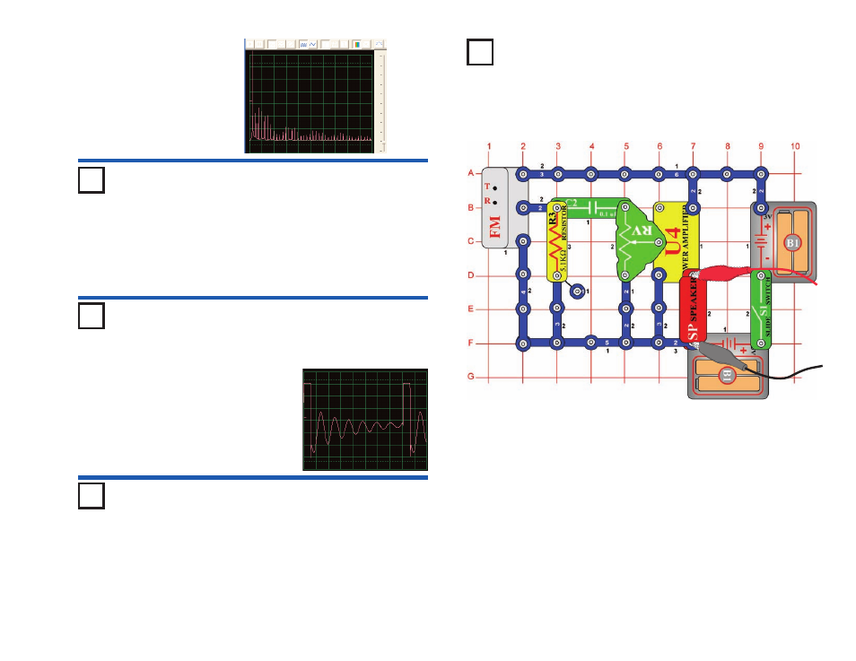
Turn on the slide switch (S1) and press the R button. Now press
the T button and the FM module scans for a radio station. When a
station is found, it locks on to it and you hear it on the speaker.
Press the T button again for the next radio station.
Connect the PC-interface cable as shown. Set up Winscope as
desired or use the same Winscope settings to view the waveform
and frequency spectrum as for project PC12 (AM radio), since the
output signal to the speaker is music or talking just like in PC12.
(AM and FM radio transmit the same types of information using
different modulation methods.) Adjust the volume using the
adjustable resistor (RV) so that all of the waveform is shown on the
Winscope screen.
Project #PC38
Adjustable FM Radio PC
OBJECTIVE: To show the output of an FM Radio.