Caution, Danger – Dunkirk DWB Series User Manual
Page 22
22
7 - GAS SUPPLY PIPING
7.1 General
• Use piping materials and joining methods acceptable
to authority having jurisdiction. In absence of such
requirements:
• USA - National Fuel Gas Code, ANSI Z223.1/NFPA
54
• Canada - Natural Gas and Propane Installation Code,
CAN/CSA B149.1
• Size and install gas piping system to provide suffi cient
gas supply to meet maximum input at not less than
minimum supply pressure. See Table 6.
• Support piping with hooks straps, bands, brackets,
hangers, or building structure components to prevent or
dampen excessive vibrations and prevent strain on gas
connection. Boiler will not support piping weight.
• Use thread (joint) compound (pipe dope) suitable for
liquefi ed petroleum gas.
• Provide sediment trap up stream of gas valve.
• Install manual main shutoff valve outside of jacket. See
fi gure 16.
7.2
Conversion To LP
Refer to Gas Conversion Kit Instructions.
CAUTION
WHAT TO DO IF YOU SMELL GAS
• Do not try to light any appliance.
• Do not touch any electrical switch; do not use
any phone in your building.
• Immediately call your gas supplier from a
neighbor’s phone. Follow gas supplier’s
instructions.
• If you cannot reach your gas supplier, call the fi re
department.
!
!
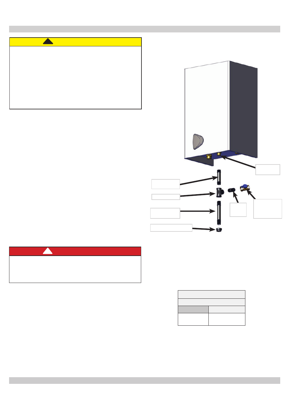
Figure 16 Manual Main Gas Shutoff Valve
Outside Boiler Jacket
With Manufacturer Suggested Piping With Drip Leg
Manufacturer suggested gas piping with drip leg.
Gas Supply Pressure
Natural Gas
Min.
Max.
3.5" w.c.
(0.7 kPa)
14" w.c. (3.3
kPa)
Table 6 - Gas Supply Pressure
DANGER
Fire Hazard. Do not use matches, candles, open
fl ames, or other methods providing ignition source.
Failure to comply will result in death or serious
injury.
!
7.3
Leak Check Gas Piping
Pressure test boiler and gas connection before placing
boiler in operation.
• Pressure test over 1/2 psig (3.5 kPa). Disconnect
boiler and its individual gas shutoff valve from gas
supply system.
• Pressure test at 1/2 psig (3.5 kPa) or less. Isolate
boiler from gas supply system by closing manual gas
shutoff valve. See fi gure 16.
• Locate leakage using gas detector, noncorrosive
detection fl uid, or other leak detection method
acceptable to authority having jurisdiction. Do not use
matches, candles, open fl ames, or other methods that
can provide ignition source.
• Correct leaks immediately and retest.
Nipple
¾” x 3” NPT
Tee ¾” NPT
Nipple ¾ x
3” NPT
¾” Pipe Cap
Gas
Connection
¾” Gas
Shutoff
Valve in ON
Postion
Nipple
¾ x 3”
NPT