Dillon Precision RL 550B User Manual
Page 12
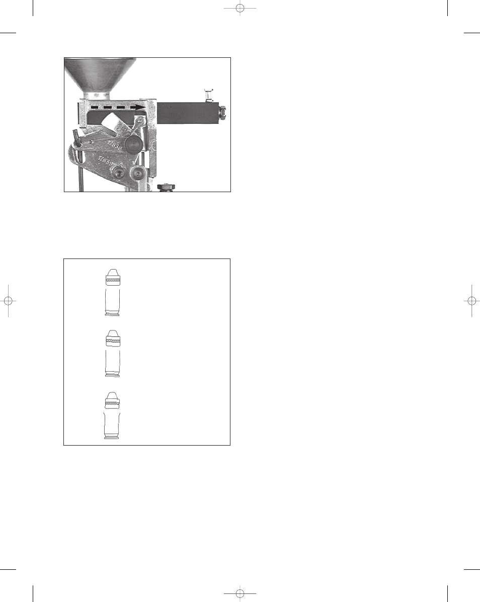
Note: If you screw the die down too far the case will look
like example “C” FIG 22. You must then discard this case,
back the powder die off, by turning it counter-clockwise,
and continue with a new sized case.
You’ll soon learn to judge the correct amount of bell by
simply looking at it. In the meantime, you might want to use
your dial calipers to check it. Twenty thousandths of an inch
greater (at the mouth of the case) than its original diameter,
should about do it.
Once you’ve achieved the desired amount of bell – with
the case in Station 2, raise the platform. Turn the die lockring
down hand tight.
Be aware that new brass will often “stick” on the powder
funnel or cause resistance on the upstroke. Cleaning the
brass in a tumbler should help.
Next, attach the powder measure fail safe rod assembly
to the bellcrank (#17839).
Using your thumb and index
finger of your right hand, move the lock-link down to
align the hole with the slot on the Powder Measure
bellcrank (#17839). Then insert the rod (#97000) through
the two holes, Fig. 20. Next,
lower the operating handle
(#20636). Insert the powder measure rod into the slot in the
return bracket (#13885) press the shoulder washer into the
slot from the bottom. Move the operating handle to the
priming position, press the operating handle firmly forward.
Tighten the blue wingnut (#13799) until the top of the spring
(#14033) just touches the underside of the return bracket
(#13885). Release the operating handle to the up/rest
position. Now, tighten the screws on the body collar clamp
(#13939).
We’ll come back to filling the measure with powder and
adjusting the bar. The purpose of the powder measure
failsafe rod (#97000) is to return the powder bar to its closed
position.
Station Three
In this station the bullet is seated to its proper depth. You
need to refer to a loading manual for overall length of the
completed round. Overall length (OAL) may vary up to
.016”, and this is normal.
Put a case into the shellplate at Station Three. Raise the
platform up and screw the die down until it just touches the
shellplate and back it out two turns. Now, back your seating
stem out.
Place a bullet on the case and operate the handle. Using
a dial caliper or case gage, check for overall length. Keep
screwing the seating stem down in small increments until the
correct overall length is achieved. Once you are satisfied
with the overall length, tighten the lock ring.
Station Four
The crimping operation is performed at this station.
Insert the crimp die and place an empty case in Station
Four. Raise the platform and screw the crimping die down
until it touches the rim of the case. Now lower the platform
and screw the die down an additional one-quarter of a turn.
Place a round in Station Four with a seated bullet and cycle
the operating handle.
You will need to refer to a loading manual to get proper
crimp dimensions for the caliber you are loading. A dial
caliper is required to take accurate measurements from your
crimped round.
If more crimp is needed, screw the crimp die down in
small increments until you get the desired crimp, now
tighten the lock ring.
* Indicates a caliber specific part. See the caliber conversion
chart on page 16 for the caliber you are loading for.
12
A
Correct amount of
bell.
B
Not enough bell.
C
Too much bell.
Fig. 22
Fig. 21 - This photo shows the large powder bar in its fully
open (rearward) position. Note the position of the white
bellcrank cube. (Primer system removed for clarity.)
RL 550B, May 2007 5/17/07 2:21 PM Page 12