Dillon Precision RL 550B User Manual
Page 11
Station Two
Here, the powder is dropped and the mouth of the case is
belled. This is where the Automatic Powder System is
installed.
The powder die is located in the automatic powder
measure assembly, you will need to retrieve it before you
can continue. See the schematic on page 4.
Now, screw the powder die (#20064) into the toolhead,
Fig. 17. Next, insert the pistol powder funnel (*#13782) or a
rifle powder funnel (*#13426) with the tapered end down,
Fig. 18. The funnel should move freely in the die.
Set the powder measure assembly onto the powder die,
Fig. 19. The powder measure clamp (#13939) should fit
loosely around the die, tighten the screws just a little. This
will enable you make adjustments to the die easily, Fig. 19.
On rifle cases, the die should be adjusted so that the
powder funnel will contact the mouth of the case and then
fully actuate the powder bar, Fig. 20 & 21. These
adjustments are accomplished with a case in the shellplate
and alternately raising and lowering the operating handle,
while adjusting the powder die, Fig. 19. When properly
adjusted, the powder bar will be moved to its full rearward
(open) position by the case,
Fig. 20 & 21, while the handle is
at the full up position. When you have determined that your
adjustments are correct, tighten the die lock ring.
On pistol cases, once the powder bar travels fully across
you should continue to adjust the powder die for the desired
amount of bell (turn the powder die 1/8 of a turn at a time).
The desired amount bell is just enough to allow the bullet to
sit on the case mouth without falling off and to keep the case
from shaving lead during the seating process (see “A” FIG
22).
Fig. 17 - This photo shows the powder die in its correct
position (Station Two) in the toolhead. The powder die
may be higher or lower depending on the caliber it is
being adjusted for
.
Fig. 18 - Drop the powder funnel into the powder die
tapered end first. The funnel should move freely in the die.
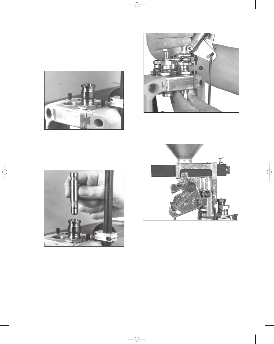
Fig. 19 - The powder die can be easily adjusted by turning
the die beneath the toolhead while holding the powder
measure securely from above.
* Indicates a caliber specific part. See the caliber conversion
chart on page 16 for the caliber you are loading for.
Fig. 20 - This photo shows the large powder bar in its closed
position. Note the position of the white bellcrank cube.
(Primer system removed for clarity.)
11
RL 550B, May 2007 5/17/07 2:21 PM Page 11