Meter display – DaySequerra UpMix User Manual
Page 12
10
UpMix User Manual
Input 1: Voltage detected on this input will cause UpMix to go into pass-though operating mode.
Input 2: Voltage detected on this input will have UpMix take the input signal and up mix it into 5.1
surround.
Input 3: Unused.
Input 4: Unused.
NETWORK - Used to update UpMix’s firmware. To connect directly to a PC without use of a network
switch or hub, a crossover cable is required. Firmware updating is accomplished via UDP Port 44600.
PSU 1 / PSU 2 - Two IEC320 ports to connect to AC Mains. The internal power supplies are auto
switching and will work on 120VAC-60Hz or 240VAC-50Hz electrical power systems with a maximum
total current draw of 25W (>.25A 120VAC or >.15A 240VAC).
Please connect UpMix to a properly grounded uninterruptible power supply (UPS) to protect
against power surges and low-voltage conditions. For maximum redundancy, connect each power
supply to a separate UPS on different power circuits. UpMix may be combined with other devices on
the output of the UPS(es) as long as the total load is within the UPS’ capacity. Consult your UPS
manual for details.
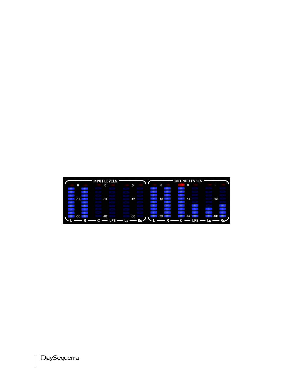
Meter Display
Figure 1. Metering display UpMix.
INPUT LEVELS – LED display shows current amplitude of input signal from -60dB to 0dB across all
active channels. Unused channels will not light the display.
L - Left (AES Input 1) LFE- Low Frequency (AES Input 4)
R - Right (AES Input 2)
Ls - Left Surround (AES Input 5)
C - Center (AES Input 3)
Rs – Right Surround (AES Input 6)
OUTPUT LEVELS – LED display shows current amplitude of signal generated by UpMix across all
active channels. Unused channels will not light the display.
L - Left (AES Output 1)
LFE- Low Frequency (AES Output 4)
R - Right (AES Output 2)
Ls - Left Surround (AES Output 5)
C - Center (AES Output 3)
Rs – Right Surround (AES Output 6)
Items in italics are only utilized when UpMix is configured to take a 5.1 audio stream and create
a 7.1 audio stream.