Clay Paky POINT MH User Manual
Page 3
3
1
2
Per rimuovere lo sporco dal vetro di
protezione della lampada (
●
) e dai filtri
colore (
❍
) usare un panno morbido
inumidito di un qualsiasi liquido
detergente per la pulizia del vetro. Non
usare solventi o alcool.
To remove dirt from the protective
glass of the lamp (
●
) and colour filters
(
❍
), use a soft cloth dipped in any
window-cleaning liquid. Do not use
solvents or alcohol.
Pour enlever la saleté s’étant
déposée sur le verre de protection de la
source lumineuse (
●
) et des filtres
couleur (
❍
), utiliser un chiffon souple
imbibé d’un liquide nettoyant
quelconque pour le nettoyage du verre.
Ne pas utiliser de solvants ou d’alcool.
Zum Entfernen des Schmutzes vom
Schutzglas der Lampe (
●
) und von den
Farbfiltern (
❍
) zu entfernen, ein
weiches, mit einem beliebigen
Glasreiniger befeuchteten Tuch reinigen. Keine Lösungsmittel oder Alkohol verwenden.
Para eliminar la suciedad del cristal protector de la lámpara (
●
) y de los filtros de
colores (
❍
), usar un paño suave humedecido con detergente líquido para vidrios. No
utilizar disolventes ni alcohol.
5
4
6
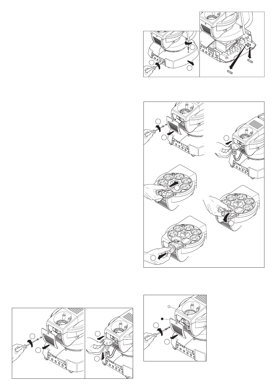
SOSTITUZIONE FILTRI COLORE
CHANGING COLOUR FILTERS
REPLACEMENT DES FILTRES COULEUR
AUSTAUSCH DER FARBFILTER
SUSTITUCIÓN DE LOS FILTROS DE COLOR
PULIZIA PERIODICA
ROUTINE CLEANING
NETTOYAGE PÉRIODIQUE
REGELMÄßIGE REINIGUNG
LIMPIEZA PERIÓDICA
Fig. A-B - Use a cable conforming to specifications EIA RS-485: 2-pole twisted, shielded,
120
Ω
characteristic impedance, 22-24 AWG, low capacity. The end connections must be
made using XLR type 3-pin male/female connectors. A terminating plug must be inserted
into the last projector with a resistance of 120
Ω
(minimum 1/4W) between terminals
2 and 3 (Fig. A) or between D+ and D– terminals (Fig. B).
Important: The wires must not make contact with each other or with the metal casing of
the connectors. The casing itself must be connected to the shield braid and to pin 1 of
the connectors.
Fig. C - Use a 4-pole flat telephone cable ending with the 4-pole connector. A terminating
plug must be inserted into the last projector with a resistance of 120
Ω
(minimum 1/4W)
between terminals 2 and 3.
Fig. A-B - Utiliser un câble conforme aux spécifications EIA RS-485: bipolaire tressé,
blindé, 120
Ω
d’impédance caractéristique, 22-24 AWG, basse capacité. Les
terminaisons doivent être réalisées avec des connecteurs mâle/femelle du type XLR à 3
broches. Il faut introduire sur le dernier appareil une fiche terminale ayant une résistance
de 120
Ω
(minimum 1/4 W) entre les bornes 2 et 3 (Fig. A) ou entre les contacts D+ et
D– (Fig. B).
Important: S'assurer que les fils n'entrent pas en contact entre eux ou avec l'enveloppe
métallique des connecteurs. Relier l'enveloppe de la fiche/prise à la gaine de blindage et
au contact 1 des connecteurs.
Fig. C - Utiliser un câble plat à 4 fils de type téléphonique se terminant avec un
connecteur à 4 broches prévu à cet effet. Il faut introduire sur le dernier appareil une
fiche terminale ayant une résistance de120
Ω
(minimum 1/4 W) entre les bornes 2 et 3.
Abb. A-B - Ein Kabel mit der Kennzeichnung EIA RS-485 verwenden: verdrilltes,
abgeschirmtes Zweileiterkabel, 120
Ω
charakteristische Impedanz, 22-24 AWG, niedrige
Kapazitä. Die Kabelabschlüsse müssen mit Steckverbindern (Steckern/Buchsen) Typ
XLR 3 pin erfolgen. Muss in das letzte Gerät der Reihe ein Endstecker mit einem
Widerstand 120
Ω
(mindestens 1/4 W) zwischen die Kontakte 2 und 3 eingesetzt werden
(Abb. A) oder zwischen den Klemmen D+ und D– (Abb. B).
Wichtig: Die Leiter dürfen weder untereinander, noch mit dem Metallgehäuse der
Steckverbinder Kontakt haben. Das Gehäuse muss mit dem Schirmgeflecht und dem
Kontakt 1 der Verbinder verbunden werden.
Abb. C - Ein flaches Vierpoltelephonkabel verwenden, dass mit einem entsprechenden 4-
Pole Verbinder endet. Muss in das letzte Gerät der Reihe ein Endstecker mit einem
Widerstand 120
Ω
(mindestens 1/4 W) zwischen die Kontakte 2 und 3 eingesetzt werden.
Fig. A-B - Utilice un cable conforme a las normas EIA RS-485: bipolar trenzado y
apantallado, 120
Ω
de impedancia característica, 22-24 AWG, baja capacidad. Las
uniones deben efectuarse con conectores macho-hembra tipo XLR de 3 pin. Es
necesario montar en el último aparato una clavija terminal con una resistencia de 120
Ω
(mínimo 1/4 W) entre los terminales 2 y 3 (Fig. A) o entre los terminales D+ y D– (Fig. B).
Importante: los cables no deben hacer contacto entre sí ni con la funda metálica de los
conectores. La funda debe conectarse a la trenza de blindaje y al pin 1 de los
conectores.
Fig. C - Utilizar cable plano de 4 polos de tipo telefónico ter minado con el
correspondiente conector de 4 polos . Es necesario montar en el último aparato una
clavija terminal con una resistencia de 120
Ω
(mínimo 1/4 W) entre los terminales 2 y 3.
SOSTITUZIONE LAMPADA
LAMP CHANGE
REMPLACEMENT LAMPE
LAMPENWECHSEL
CAMBIO LÁMPARA
1
2
3
4
SOSTITUZIONE FUSIBILI
REPLACING FUSES
REMPLACEMENT FUSIBLES
AUSWECHSELN DER SICHERUNGEN
CAMBIO DE LOS FUSIBLES
1
2
6,3 AT
5 x 20 mm fuse
2 AT
5 x 20 mm fuse
1
2
3
Accensione proiettore: Dopo aver eseguito tutte le operazioni indicate
precedentemente, alimentare l’apparecchio verificando che abbia inizio la procedura di
azzeramento.
Switching on the projector: After having carried out all the operations described
above, switch on the appliance to check that the resetting has begun.
Allumage projecteur: Après avoir effectué toutes les opérations indiquées
précédemment, mettez l'appareil sous tension en vous assurant que la procédure de
mise à zéro a commencé.
Einschalten des Projektors: Nach Abschluss der zuvor angezeigten Operationen das
Gerät speisen und prüfen, ob der Ablauf der Nullstellung begonnen hat.
Encendido del proyector: Después de haber llevado a cabo todas las operaciones
indicadas anteriormente, alimente el aparato comprobando que se inicie el
procedimiento de puesta a cero.