Bimba STP-AC5 User Manual
Page 2
CONTENTS
Step 3
a)
Apply power to the drive.
b)
Follow the configuration instructions in the IQ
®
Stepper help screens. The
IQ
®
Stepper software can be used to set up your drive for operation in
several different modes including: pulse & direction, analog velocity, SCL,
and IQ programming. IQ
®
Stepper includes a self test option (under the
Drive menu) to verify that the motor and power supply are correctly wired
and configured.
c)
For IQ models, use IQ
®
Programmer to build and test your program.
Step 5
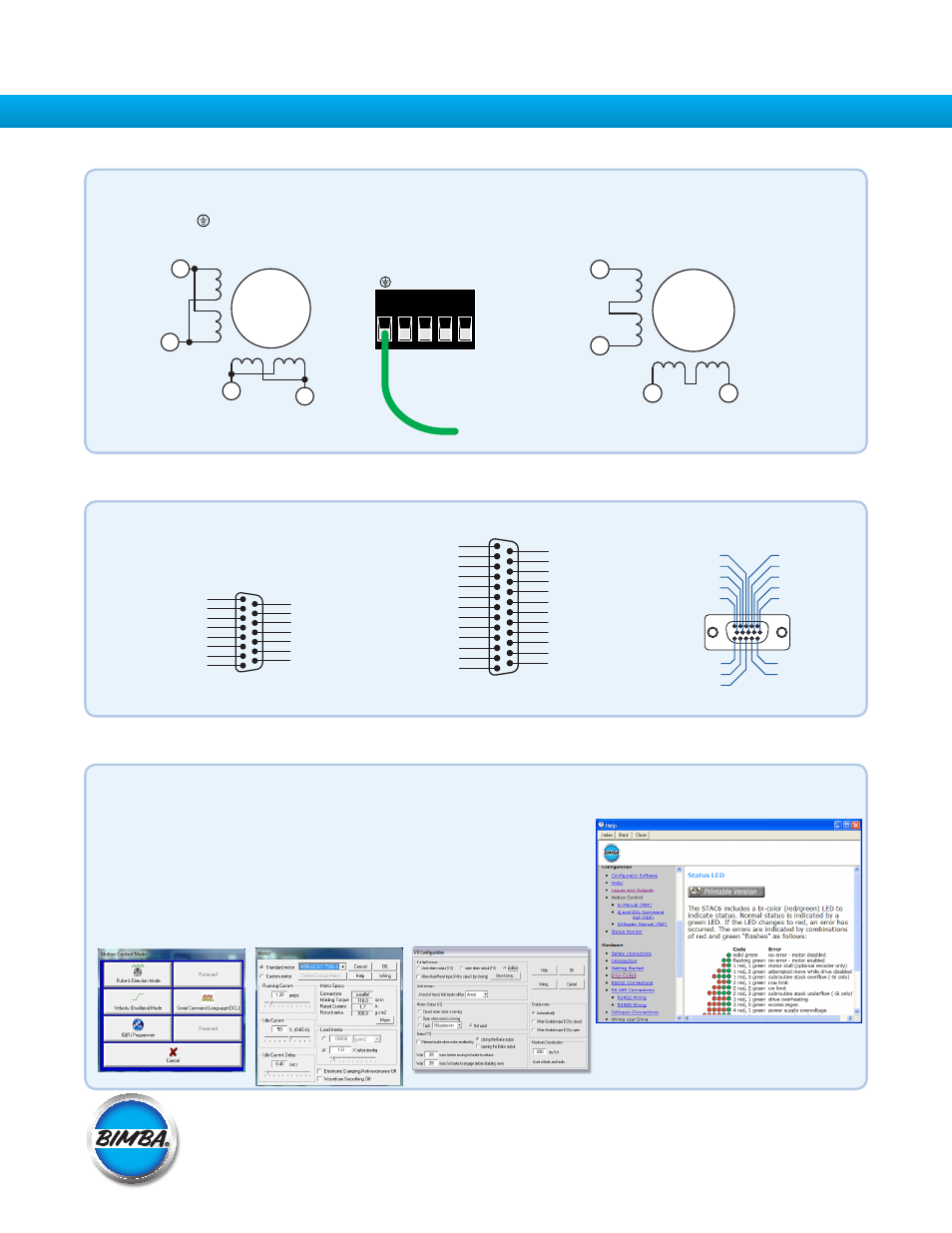
Connect the drive to the motor. If you are using one of the recomended Bimba motors, connect the motor in parallel to the
STP-AC5-*-1 and in series to the STP-AC5-*-2, as shown below. Be sure to connect the motor case ground to the STP-AC5
ground terminal.
For a non-Bimba motor, please refer to your motor specs for wiring information.
Series Connection
220V Drive
Parallel Connection
120V Drive
a)
Connect the I/O
b)
Connect the Encoder (optional)
Step 4
X COMMON
X3 / Enable
X5 / CW JOG
X4 / Alarm Reset
Analog IN
Analog IN
X2 / DIR -
X2 / DIR +
X1 / STEP+
X1 / STEP -
GND
GND
X8/CCW LIMIT -
X8/CCW LIMIT+
X7/CW LIMIT -
X7/CW LIMIT+
Y4 -
Y4+
+5V OUT
Y COMMON
Y3 / FAULT
Y2 / MOTION
Y1 / BRAKE
18
17
16
15
14
13
12
11
10
9
8
7
6
5
4
2
3
1
19
20
21
22
23
24
25
X6 / CCW JOG
IN/OUT - ST5/10 - Q/Si
Z+ (5)
NC (10)
B- (4)
NC (9)
B+ (3)
NC (13)
NC (14)
NC (15)
(12) NC
(11) NC
(6) Z-
(1) A+
(7) +5VDC 200mA
(2) A-
(8) GND
PC GND
PC TX-/RX- or B
PC TX+/RX+ or A
+RX- +TX- GND
Drive 1
Drive 2
Drive 3
+RX- +TX- GND
+RX- +TX- GND
PC GND
PC RX-
PC RX+
PC TX-
PC TX+
+RX- +TX- GND
Drive 1
Drive 2
Drive 3
+RX- +TX- GND
+RX- +TX- GND
ENCODER
*OPTIONAL
A+
A–
B+
B–
8
lead
motor
White
Orange
Brown
Green
Red
Yellow
Blue
Black
8
lead
motor
White
Brown
Orange
Green
Red
Blue Yellow
Black
B+
A+
A–
B–
X4+
X4-
Y1/FAULT+
Y1/FAULT-
Y2+
Y2-
ANALOG IN
X1/STEP+
X1/STEP-
X2/DIR+
X2/DIR-
X3/EN+
X3/EN-
GND
+5V OUT
100mA MAX
1
2
3
4
5
6
7
8
9
10
11
12
13
14
15
IN/OUT 1
This connector is included
on all models.
OUT1+
OUT2+
OUT3+
OUTCOM
+5V OUT, 100mA MAX
GND
OUT4+
OUT4-
IN7+
IN7-
IN8+
IN8-
N/C
N/C
N/C
IN6
IN5
IN4
IN3
INCOM
IN2-
IN2+
IN1-
IN1+
GND
1
2
3
4
5
6
7
8
9
10
11
12
13
14
15
16
17
18
19
20
21
22
23
24
25
IN/OUT 2
This connector is included on
IQ models.
To Motor Case
A+ A- B+ B-
Form QSG-STP-AC5-040B
Bimba Manufacturing Company
P.O. Box 68 Monee, Illinois 60449-0068
Phone: 708-534-8544 Toll Free: 800-44-BIMBA Fax: 708-235-2014
Email: [email protected] www.bimba.com