4 i/o connectivity table, 5 block diagrams, Cpci-3e10 block diagram – ADLINK cPCI-3E12 User Manual
Page 15: I/o connectivity table, Block diagrams, Figure 1-1: cpci-3e10 block diagram, 4 i/o connectivity table 1.5 block diagrams, Introduction 3 cpci-3e10
Introduction
3
cPCI-3E10
1.4
I/O Connectivity Table
1.5
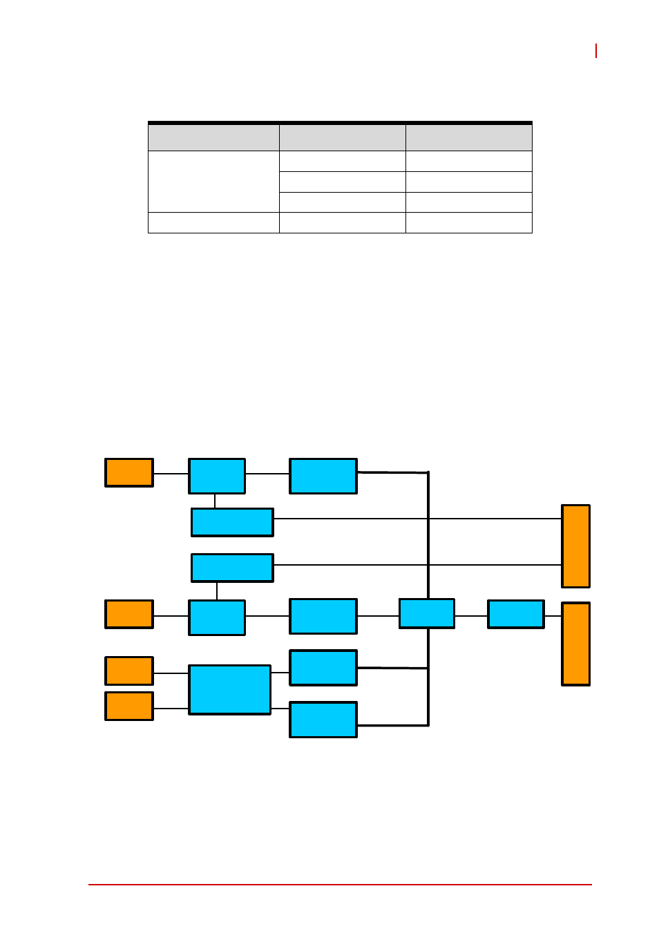
Block Diagrams
cPCI-3E10 Block Diagram
The cPCI-3E10 is based on four Intel® 82574L PCI express Giga-
bit Ethernet controllers. The Intel® 82574L is a highly integrated
chip including Ethernet MAC and PHY. Please refer to the Intel®
82574L datasheet for more information.
Figure 1-1: cPCI-3E10 Block Diagram
Function
Model
Faceplate
GbE (RJ-45)
cPCI-3E10
Y x4
cPCI-3E12
Y x2
cPCI-R3E10
Y x2
Fast Ethernet (DB-9)
cPCI-3E10-SUB
Y x2
LAN2
LAN1
LAN3
LAN4
Switch
Switch
Transformer
PEX8608
PI7C9X130
J1
J2
PCIE x4
PCIE x1
PCIE x1
PCIE x1
PCIE x1
GbE
GbE
Transformer
Transformer
Intel
82574L-B
Intel
82574L-C
Intel
82574L-D
Intel
82574L-A
GbE
GbE
This manual is related to the following products: