ADLINK cPCIS-ET2600 Series User Manual
Page 13
Backplane
• 7
The handle on CompactPCI cards and PSUs ensures simple and safe
installation and removal. Please follow the procedures below to install a
CompactPCI module into a cPCIS-ET2600 Series chassis with CompactPCI
PSU(s):
CompactPCI Card Installation/Removal Procedure
1. Place the subsystem on a level surface or rackmount it. Remove the
blanking plates where required by undoing the retaining screws at each
end. Retain the blanking plates for possible future use. The system should
not be put into use without blanking plates for all empty slots, otherwise the
EMC and cooling performance will be compromised
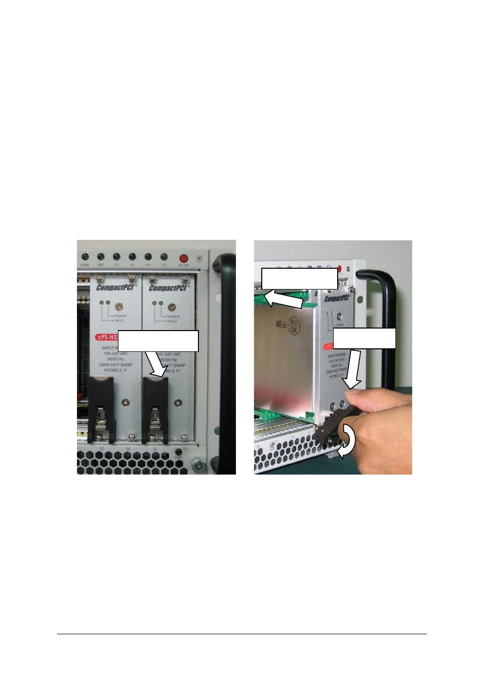
2. Hold the SBC module, peripheral card or PSU module vertically. For PSU
modules, make sure that the handle is unlatched (i.e. that it is pulled
downwards) by first pressing on the locking button with your thumb.
3. Carefully insert the module into the desired slot by sliding the edges of the
board into the appropriate card guide rail. Take care to ensure correct
alignment of the card with the chassis during insertion to prevent damage
to the card and/or backplane.
4.
Continue inserting the card until the handle engages with the chassis.
5. Pull upwards on the handle for final insertion. For PSU modules, ensure
that the locking button on the handle is fully latched into position.
Locking Button
Unlatched
Insert Module