4 trigger bus – ADLINK PXI-7921 User Manual
Page 30
24 • Operation Theorem
module.
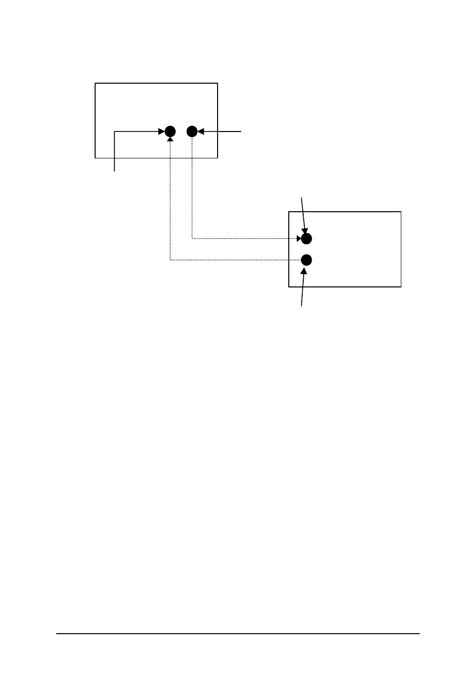
Figure 12: Signal Connection between Switch Module and Agilent DMM
For more information on scanlist configuration, scan mode setup, start, and
stop functions of the auto-scanning process, please refer to the software
programming users’ guide.
4.4 Trigger Bus
PXI specification defines eight bused-lines across slots in a segment. Users
can route various trigger signal to synchronize multiple PXI instruments, and/or
simplify field wiring across multiple ADLINK Switch Modules.
On ADLINK Switch Modules, the trigger bus driver is disconnected from PXI
trigger bus before users’ configuration.
Figure 13 illustrates the available signal destinations for Trigger Bus[7..0].
Signal names in the solid-line boxes represent the external (physical) signals
on connectors while signals in the dotted-line boxes represent the switch
module’s internal signal.
ADLINK
PXI Switch module
Agilent 33401A
6-1/2 DMM
Wiring
Scanner Advanced Output
(S_ADV)
Trigger Input
(TRG_IN)
External Trigger Input
(Trig In)
Measurement Complete
(VM Comp)