ADLINK PXI-7921 User Manual
Page 18
12
•
Signal Connection
46. COM3-
26. CH9A-
4. CH1A-
47. CH6B+
27. CH10A+
5. CH2A+
48. CH6B-
28. CH10A-
6. CH2A-
49. CH7B+
29. CH11A+
7. CH3A+
50. CH7B-
30. CH11A-
8. CH3A-
51. CH8B+
31. CH0B+
9. CH4A+
52. CH8B-
32. CH0B-
10. CH4A-
53. CH9B+
33. CH1B+
11. CH5A+
54. CH9B-
34. CH1B-
12. CH5A-
55. CH10B+
35. CH2B+
13. COM0+
56. CH10B-
36. CH2B-
14. COM0-
57. CH11B+
37. CH3B+
15. COM1+
58. CH11B-
38. CH3B-
16. COM1-
59. 1WireloRef*
39. CH4B+
17. CH6A+
60. TRG_IN
40. CH4B-
18. CH6A-
61. S_ADV
41. CH5B+
19. CH7A+
62. SHDNn
42. CH5B-
20. CH7A-
21.
GND
*not used in four-wire mode
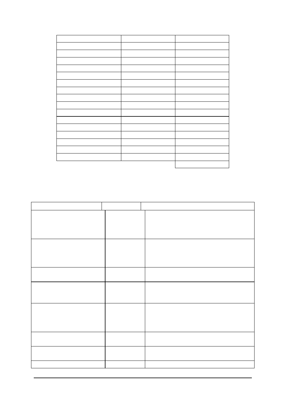
Table 3: Pin Assignment (4 wire)
Signal Name
Type
Description
COM0± (one wire)
COM<0..3>± (two wire)
COM<0..1>A±(four wire)
COM<0..1>B± (four wire)
Input/Output Common---The common for each bank.
CH<0..47> (one wire)
CH<0..23>± (two wire)
CH<0..11>A± (four wire)
CH<0..11>B± (four wire)
Input/Output Channels---Where signals are connected
to the switch card. CHχ+ and CHχ- are
switched together.
1WireLoRef
Input/Output 1 Wire Low Reference---The common
reference signal used in one-wire mode.
TRG-IN
Input
Trigger Input---Trigger from an
instrument to advance the switch card to
the next scan entry.
S_ADV Output
Scanner
Advanced---Trigger
to
an
instrument that indicated the switch card
has advanced to the next scan and relays
are debounced.
SHDNn Input
Emergency
Shutdown---The trigger used
to shutdown the system.
+5V OUT
Output
+5V VDC Source---Provide +5 power
pin.
GND
Output
Ground---Provide system ground pin.