Lpci/lpcie-7250 cn1 pin assignment, Table 2-5: lpci/lpcie-7250 cn1 pin assignment, Installation 27 – ADLINK PCI-7251 User Manual
Page 35
Installation
27
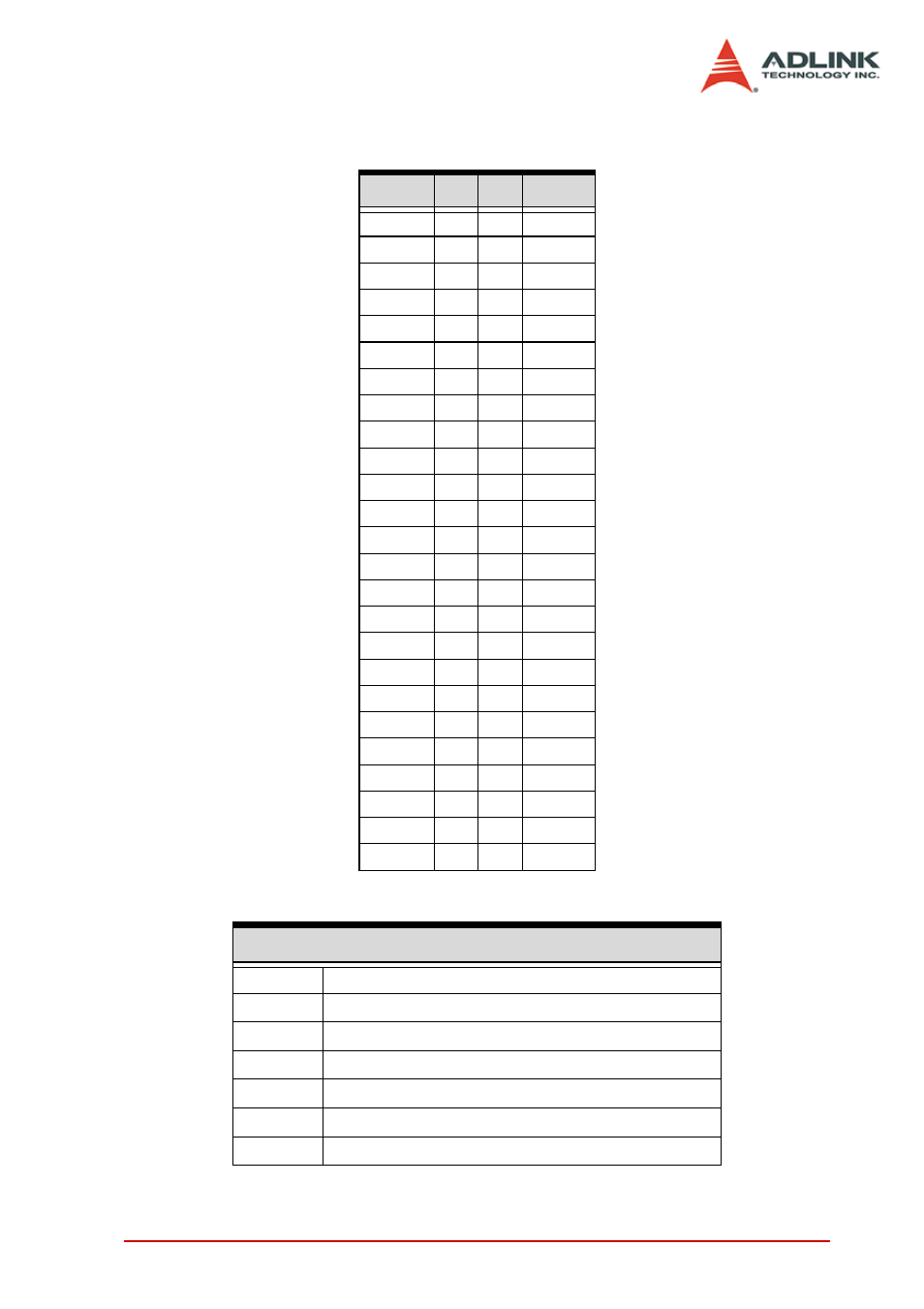
LPCI/LPCIe-7250 CN1 Pin Assignment
Signal
Pin
Pin
Signal
NO0
1
26
NO4
COM0
2
27
COM4
NC0
3
28
NC4
NO1
4
29
NO5
COM1
5
30
COM5
NC1
6
31
NC5
NO2
7
32
NO6
COM2
8
33
COM6
NC2
9
34
NC6
NO3
10
35
NO7
COM3
11
36
COM7
NC3
12
37
NC7
N/C
13
38
N/C
N/C
14
39
N/C
N/C
15
40
N/C
N/C
16
41
N/C
N/C
17
42
N/C
IDI_0H
18
43
IDI_0L
IDI_1H
19
44
IDI_1L
IDI_2H
20
45
IDI_2L
IDI_3H
21
46
IDI_3L
IDI_4H
22
47
IDI_4L
IDI_5H
23
48
IDI_5L
IDI_6H
24
49
IDI_6L
IDI_7H
25
50
IDI_7L
Table 2-5: LPCI/LPCIe-7250 CN1 Pin Assignment
Legend
Din:
Digital input channel n
IGND:
Ground of DIn signals
DinH:
Digital input channel n with positive polarity
DinL:
Digital input channel n with negative polarity
NC n:
Normal close pin of relay n
NO n:
Normal open pin of relay n
COM n:
Common pin of relay n
This manual is related to the following products: