Nstallation, Pecifications – Dacor 100500 User Manual
Page 10
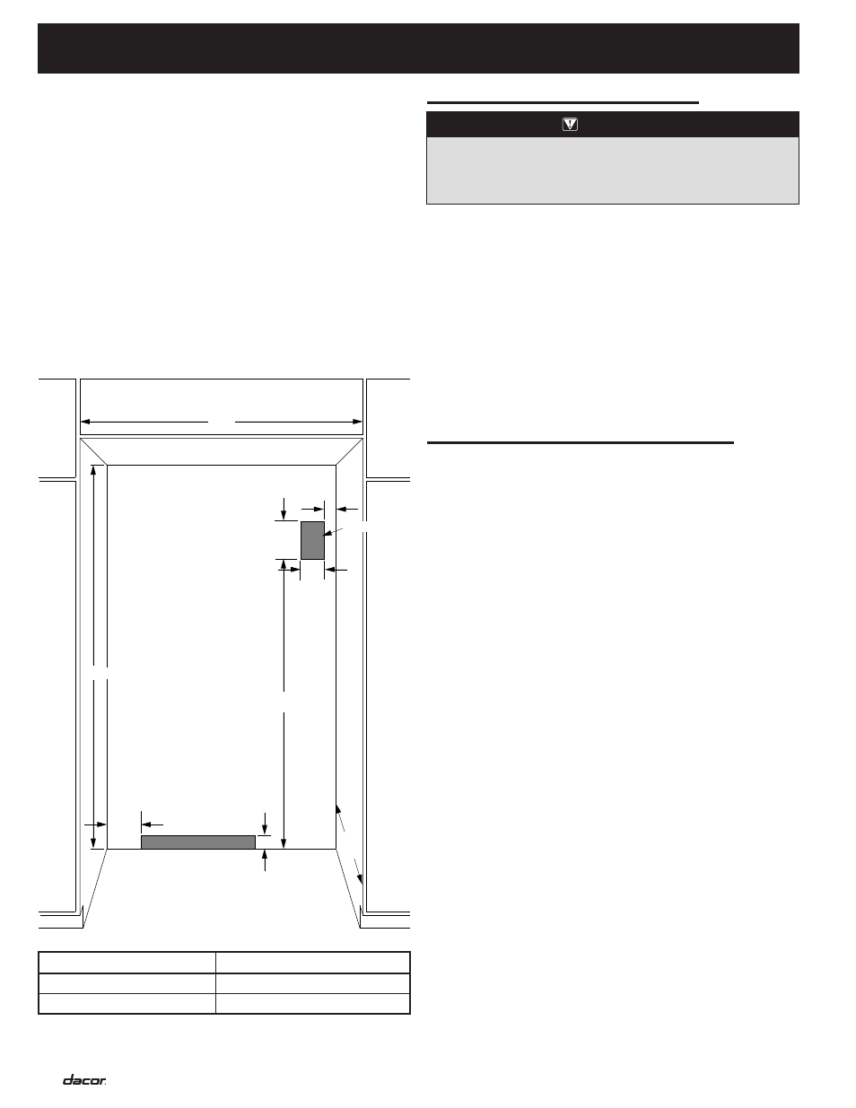
Rough-In Dimensions
◊
The solid sofit or ceiling should be within 1” (25mm) above
the refrigerator. If the solid sofit is higher than 1” (25mm) or
one is not available, then the refrigerator must be braced to
prevent tipping during use. If the anti-tip blocking is need.
(see “Anti-Tip Blocking” on page 9)
NOTE:
A clearance of 1/2” (13mm) must be maintained above
the top grill in order for the top grill to be opened.
◊
A grounded 3 prong non-GFCI electrical outlet should be
placed 2” (51mm) from the right side cabinets or end panel.
See “Electrical Requirements” for additional information.
◊
The plumbing for the water line can come through the floor
or the back wall. See “Water Supply Requirements” for more
information.
i
nsTallaTion
s
PeCifiCaTions
7”
4”
2”
6”
3”
75 1/2”
“A”
83 3/4”
Water Supply
Electrical
24”
e
leCTRiCal
R
equiRemenTs
A 115VAC, 60 Hz, 15 Amp circuit breaker and electrical supply are
required. A separate dedicated non-GFCI circuit, servicing only
this appliance, is required.
Your Dacor
®
Built-In refrigerator is equipped with a 40” (1016mm)
3-prong grounded power cord, which must be plugged into a
3-prong grounding-type non-GFCI wall receptacle. Follow the
National Electrical Code and local codes and ordinances when
installing the receptacle. See “Rough-In Dimensions” for location
of the electrical supply.
IMPORTANT:
A ground fault circuit interrupter (GFCI) is not
recommended and may cause interruption of operation.
WARNING
ELECTRICAL SHOCK HAzARD – Plug into a grounded 3-
prong non-GFCI outlet. Do not remove ground prong. Do not
use an adapter. Do not us an extension cord. Failure to do so
can result in death, fire, or electrical shock
.
◊
All installations must meet local plumbing code
requirements.
◊
Connect to 1/4” (6mm) copper line to the house cold fresh
water supply.
◊
Use a shut off valve between the refrigerator and supply.
The shut off valve should be a drilled saddle valve.
◊
Do not use a self-tapping valve which reduces water flow
and clogs more easily.
◊
Route the water line within 3-1/2” (89mm) of the rear wall
and no higher than 3” (76mm) from the floor.
◊
Allow a minimum of 24” (610mm) dimeter service loop of
copper tubing outside the wall or floor for easy connection to
the water supply.
Cold water supply
Connect the ice maker to a cold water line with water pressure
between 30 and 120 PSI. If you have any questions about your
water pressure, call your utility company.
IMPORTANT:
◊
In homes with a Reverse Osmosis water treatment system,
remove the water inlet connector from the “yellow” valve
and attached to the “blue” valve. Make sure the water filter
bypass plug is in place.
w
aTeR
s
uPPly
R
equiRemenTs
Model
Rough-In Width “A”
42-Inch
41 1/2”” (1054mm)
48-Inch
47 1/2”” (1207mm)