Acrosser AR-B1320 User Manual
Page 34
A
A
R
R
-
-
B
B
1
1
3
3
2
2
0
0
U
U
s
s
e
e
r
r
’
’
s
s
G
G
u
u
i
i
d
d
e
e
3-14
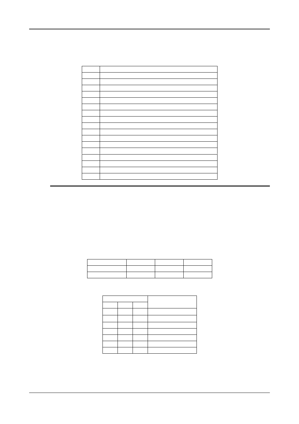
3.15.2 WD REPORT REGISTER - INDEX 38H
This register is used to select the watchdog report when the watchdog times out.
Bit 7-4 Watchdog Timer Time-out Report Signal Select
0000
No output signal
0001
IRQ3 selected
0010
IRQ4 selected
0011
IRQ5 selected
0100
IRQ6 selected
0101
IRQ7 selected
0110
IRQ9 selected
0111
IRQ10 selected
1000
IRQ11 selected
1001
IRQ12 selected
1010
IRQ14 selected
1011
IRQ15 selected
1100
NMI selected
1101
System reset selected
1110
No output signal
1111
No output signal
Bit 3-0
Other function. Please do not modify these bits.
Note 1):If you program the watchdog to generate an IRQ signal when it times out, you should initialize
the IRQ interrupt vector and enable the second interrupt controller (8259 PIC) in order to enable
the CPU to process this interrupt. An interrupt service routine is required too.
2) Before you initial the interrupt vector of the IRQ and enable the PIC, please enable the
watchdog timer previously, otherwise the watchdog timer will generate an interrupt at the time the
watchdog timer is enabled.
3.15.3 WD TIMER COUNTER(24 BITS) - INDEX 39H, 3AH, AND 3BH
These registers are used to set the desired counter for the watchdog to count down. The time base of each
count is 30.5£ g
sec.
INDEX
3Bh
3Ah
39h
Data Bit
D7 …D0
D7 …D0
D7 …D0
24-bit Counter
D23 …D16
D15 …D8
D7 …D0
For example:
INDEX
3Bh
3Ah
39h
Watchdog Timer
00h
00h
01h
30.5 £ g
sec
00h
00h
02h
61.0 £ g
sec
00h
01h
00h
7.8 m sec
00h
02h
00h
15.6 m sec
01h
00h
00h
2 sec
02h
00h
00h
4 sec
0FFh 0FFh 0FFh
512 sec