Altec Lansing 1270 User Manual
Page 3
Attention! The text in this document has been recognized automatically. To view the original document, you can use the "Original mode".
OUTPUT
■0"
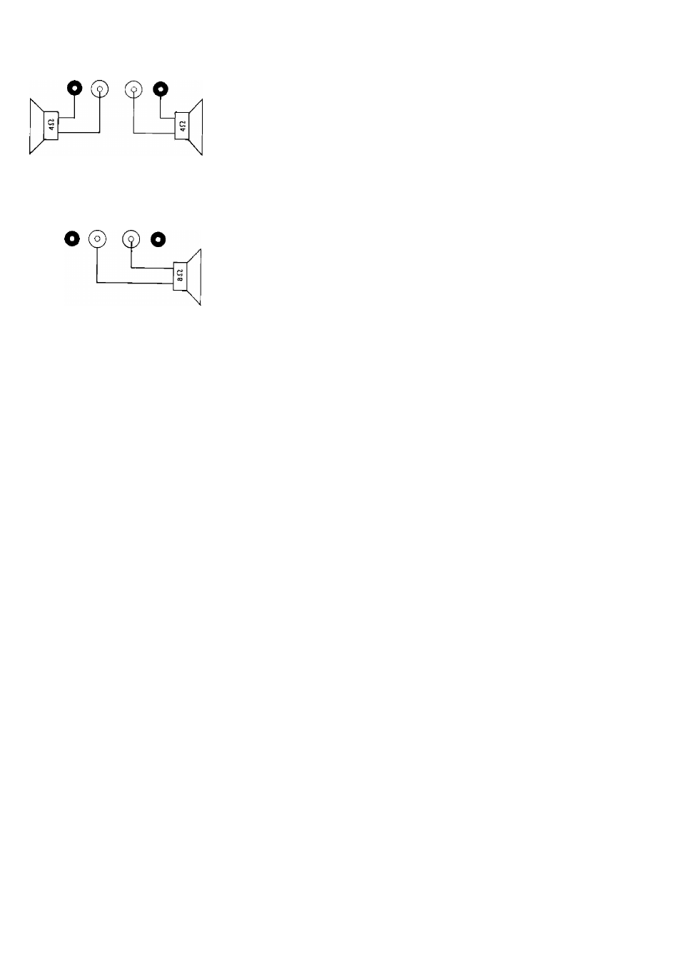
3a. Independent Operation of
L and R Channels
NOT CONNECTED
0" "0-
NOT CONNECTED
STEREO (INDEPENDENT CHANNEL)
OPERATION
1. After Installation and hookup of connec
tions as in Figure 3A, check that the
BRIDGE/NORMAL switch is positioned
at NORMAL, and that the LEFT and
RIGHT CHANNEL volume controls are
turned fully counterclockwise. (°°).
2. Set input signal level to the 1270 at a
nominal value of 0.775V.
3. Turn on ac line POWER switch and note
illumination of POWER indicator.
4.
Turn LEFT and RIGHT CHANNEL vol
ume controls clockwise until desired
output power is obtained. If either LEFT
or RIGHT peak/error indicator illumi
nates, reduce output level with channel
volume control or reduce input level to
1270.
3. Turn on ac line POWER switch and note
illumination of POWER indicator.
4. Turn LEFT OHANNEL volume control
clockwise until desired output power is
obtained. Be sure to leave RIGHT CHAN
NEL volume control fully counterclock
wise. If LEFT peak/error indicator illu
minates, reduce output level with LEFT
CHANNEL volume control, or reduce
input level to the 1270.
CAUTION
Bridged operaton provides a true bal
anced output. Do not connect either
side of the loudspeaker line to audio
common or to any other “ground”
connection.
3b. Bridge Operation of
L and R Channels
Figure 3. Output Connections
BRIDGE (MONO) OPERATION
1. After installation and hookup of connec
tions as in Figure 3B, check that the
BRIDGE/NORMAL switch is positioned
at BRIDGE, and that the LEFT and
RIGHT CHANNEL volume controls are
turned fully counterclockwise {“).
2. Set input signal level to the left (L) INPUT
of the 1270 at a nominal value of 0.775V.
(The right (R) INPUT is left unconnected.)
—3—