Diamond Power Products MM-48-AT User Manual
Page 13
Diamond-MM-48-AT User Manual V1.01
Page 13
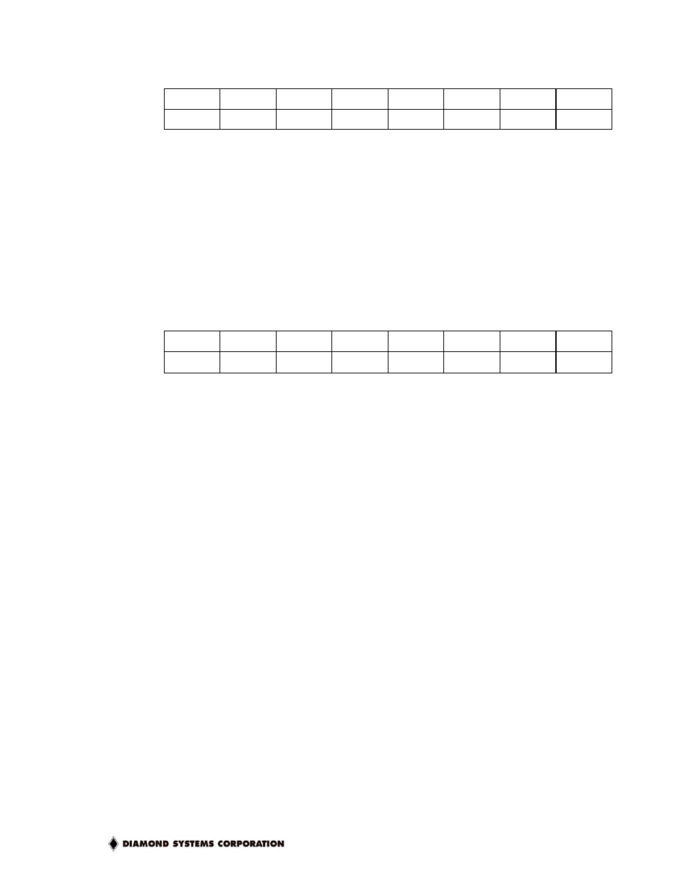
Base + 3
Read/Write
Relay Control Port
Bit
No.
7 6 5 4 3 2 1 0
Name RELAY7 RELAY6 RELAY5 RELAY4 RELAY3 RELAY2 RELAY1 RELAY0
These bits control the 8 relays. 0 = off (C connected to NC), 1 = on (C connected to NO). The
written value may be read back with true logic. The value on the corresponding output pin is
the inverse of the value in this register.
On power-up or reset, the output register is cleared to all zeroes and all relays reset to their
off condition (C connected to NC) by resetting all RELAY pins to 1. Relays are in the off
condition when power is off and remain in that condition when power is applied until a 1 is
written to their corresponding control register bit.
Base + 4
Read/Write
Digital I/O Configuration Register
Bit
No.
7 6 5 4 3 2 1 0
Name
DIR3
DIR2
DIR1
DIR0
Definitions:
DIR3-0
Digital I/O direction settings for each bit: 1 = output, 0 = input
All digital I/O lines are in input mode on power-up.