Commissioning, 7commissioning, 1 general – Dimplex LA 16TR User Manual
Page 7: 2 preparatory steps, 3 procedure
7
COMMISSIONING
7
COMMISSIONING
7.1
General
To ensure proper commissioning it should be
carried out by an after-sales service authorized by
the manufacturer. Only then can an extended
warranty period of 3 years in total be granted (cf.
Warranty service).
7.2
Preparatory Steps
Prior to commissioning, the following items need to
be checked:
- All connections of the heat pump must have been
made as described in Chapter 6.
- In the heating circuit all valves that could impair
the proper heating water flow must be open.
- T h e a i r i n t a k e / d i s c h a r g e p a t h m u s t b e
unobstructed.
- The sense of rotation of the fan must correspond
to the direction of the arrow.
- An operating mode must have been set on the
remote control.
- Proper condensate drainage must be ensured.
7.3
Procedure
The
start-up of the heat pump is effected via the
remote control.
Where an overflow valve is fitted to assure the minimum
heating water flow rate, the valve must be set in
accordance with the specific requirements of the heating
installation. An incorrect setting may result in various
error symptoms and an increased electric power
consumption. To correctly set the overflow valve, the
following procedure is recommended for the "heating
mode":
Close all of the heating circuits that may also be closed
during operation (depending on the type of heat pump
usage) so that the least favourable operating state -
with respect to the water flow rate - is achieved.
Typically these are the heating circuits of the rooms
on the building's south and west sides. At least one
heating circuit must remain open (e.g. bathroom).
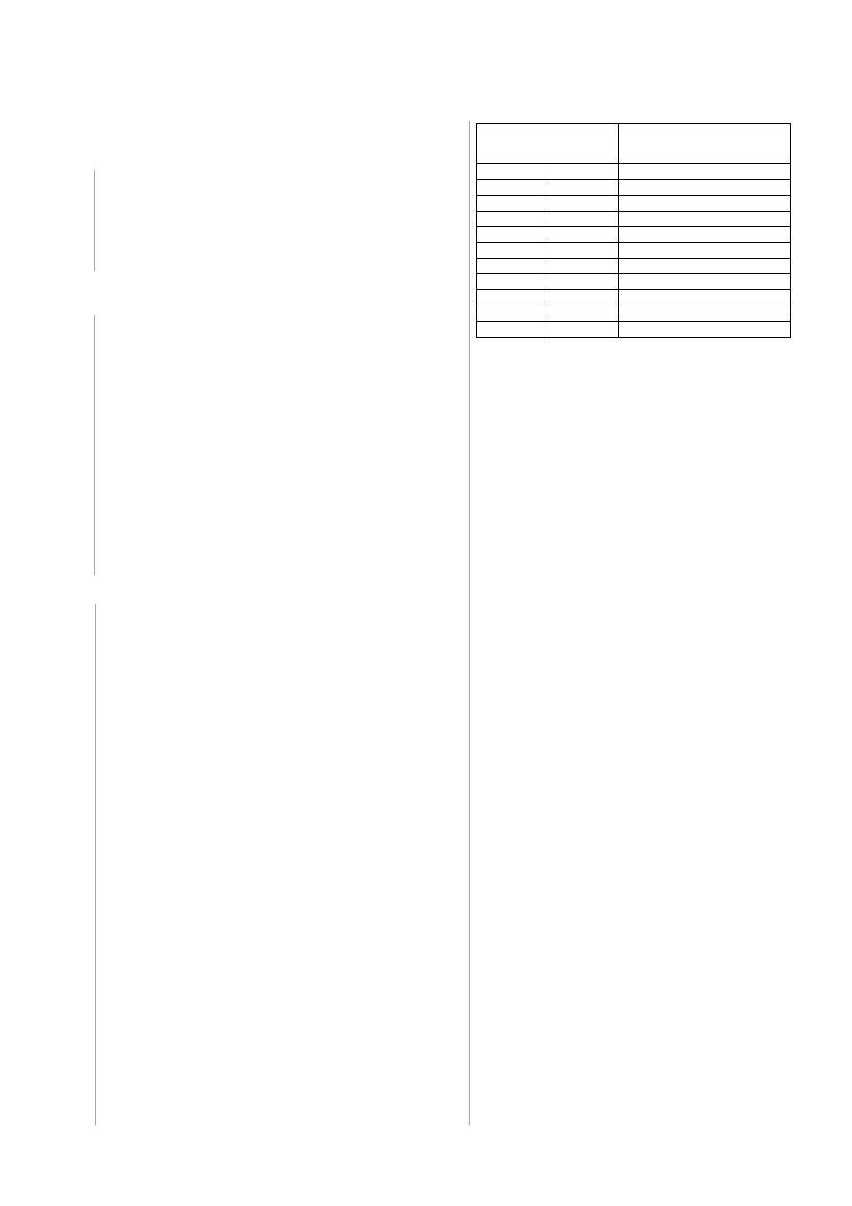
The overflow valve is to be opened to such an extent
that based on the current heat source temperature
the maximum temperature spread between heating
supply and return flow temperature is obtained, as
indicated in the table that follows. The temperature
spread should be measured as closely to the heat
pump as possible. In mono-energetic systems, the
electric heating element is to be deactivated.
Heat source temperature
from to
max. difference between
heating water supply and
return temperature
-20 °C
-15 °C
4 K
-14 °C
-10 °C
5 K
-9 °C
-5 °C
6 K
-4 °C
0 °C
7 K
1 °C
5 °C
8 K
6 °C
10 °C
9 K
11 °C
15 °C
10 K
16 °C
20 °C
11 K
21 °C
25 °C
12 K
26 °C
30 °C
13 K
31 °C
35 °C
14 K
The following procedure must be observed so that
the commissioning activities can be carried out
without any problems:
a)
Close all heating circuits.
b)
Open the overflow valve all the way.
c)
W a i t u n t i l t h e b u f f e r t a n k h a s r e a c h e d a
temperature of approx. 25 °C.
d)
Subsequently, slowly reopen the valves of the
heating circuits, one after the other, in such a
w a y t h a t t h e h e a t i n g w a t e r f l o w r a t e i s
continually increased by slightly opening the
related heating circuit. When so doing, the
heating water temperature in the buffer tank
must not fall below 20 °C so that the heat pump
can be defrosted at any time.
e)
Once all heating circuit are fully open and a
heating water temperature of approx. 20 °C is
maintained in the buffer tank, the minimum flow
rate must be set on the overflow valve and the
heating circulating pump.