Aiphone BX-1200 User Manual
Page 5
Attention! The text in this document has been recognized automatically. To view the original document, you can use the "Original mode".
BX-600, *1200:
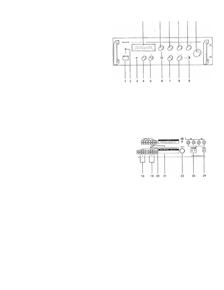
1) Power Switch
2) Power Indicator (LED)
3) Overload Indicator (LED)
4) BASS Tone Control
5} TREBLE Tone Control
6)MIC-1 Input Phone Jack
7}AUX'1 Volume Control
8) AUX-2/PHONO Volume Control
9) AUX-2/PHONO Select Switch
10) PEAK Indicator (LED)
11) MIC-1 Volume Control
12) M lC-2 Volume Control
13) MIC‘3 Volume Control
14) MIC4/PHONE Volume Control
15) MASTER Volume Control
16) GROUND Terminal
17) MIC-2 Input XLR Receptacle
18) MIC-4 Input Terminals
19) MiC-3 Input Terminals
20) M1C4/PHONE Select Switch
21) PHONE Input Terminals
22) AC Fuse (2.5A for BX-600, 5A for BX-1200)
23) AC Outlet (Maxv 100W, unswitched)
24) AC Power Supply Cord
25) PHONO Input Jacks
26) AUX*2 Input Jacks
27) AUX-1 Input Jacks
28) AUTO/MANUAL Muting Control Select Switch
29) Manual Muting Control Terminals
30) Muting Level Control
31) Line Output Jack
32) Low Impedance Output Terminals
33) Constant Voltage Output Terminals
1 0
11
1 2
13
14
15
25
26 27
28 29 30
31 32
33
BBS"
© @ ® ©
16
17
INSTALLATION ^
Unpacking:
Upon receiving unit(s), please inspect for any damage incurred in transit. If damage is found, please notify
your Aiphone Distributor or representative immediately.
Connections:
An AM/FM tuner, cassette player, remote microphone, chime or other high level signal source may be
connected to high impedance inputs with a single-conductor low capacitance shielded cable.
A high impedance microphone with a single conductor shielded cable of 30' to 60' (10 to 20m) length
can be plugged into the MIC-1 input on the front panel.