Altec Lansing 3300A User Manual
Page 9
Attention! The text in this document has been recognized automatically. To view the original document, you can use the "Original mode".
Operating Instructions for the Altec Lansing 3300A Series Mixing Consoles
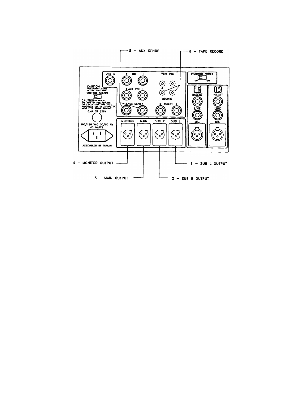
figure 7. Rear panel output connectors.
7.
INSERT L and R (SUB L
and SUB R): A space-saving
3-conductor (stereo) phone jack
is used for both output from
SUB L and SUB R respectively,
emd for the return to the
mixer’s master section from an
external processing device. Be
sure that the device that is to
be patched in heis line level
unbalanced inputs and outputs.
The signal at the insert jack can
drive loads of 2000 ohms or
greater
and
the
external
processing device should have a
low output internal impedance
(100 ohms or less). Refer to
Section 3.3 of this manual and
Figure 3 for proper connections.
A nominal input signal is a level
of -1-4 dBu; the maximum level
is -(-20 dBu.
8.
Input Channel INSERTs: A
space-saving,
3-conductor
(stereo) phone jack is used for
both output from the input
channel and for the return to
the input channel from an
external processing device. Be
sure that the device that is to
be patched in has line level
unbalanced inputs and outputs.
The signal at the insert jack can
drive loads of 2000 ohms or
greater and the external pro
cessing device should have a low
output internal impedance (100
ohms or less). Refer to Section
3.3 of this manual and Figure 3
for proper connections.
A nominal input signal is a level
of -f4 dBu; the maximum level
is -1-20 dBu.
4.4 Rear Panel Output Connec
tions (Refer to Figure 7.)
In the 3300A series mixers, the SUB
L, SUB R. MAIN, and MONITOR
outputs are servo-balanced and made
through chassis-mount male 3-pin
XLR-tyf>e connectors to a meiximum
level of -1-24 dBu (12.3 Vrms).
All other output connections are line
level, unbalanced, and made through
standard V4-inch phone jacks (except
for RECORD OUT).
1.
SUB L Output: This left sub
group output is derived by sum
ming all of the points (channels
and externa'.) assigned to the
left subgroup bus. A PAN con
trol rotated fully counterclock
wise to the ’L” position will
assign that signal only to the
left bus.
2.
SUB R Output: This output is
the right subgroup equiveJent of
the SUB L output.
3. MAIN Output:
The MAIN
output is the summed mix of
ALTEC LANSING^ CORPORATION • a Mark IV Company