Dimplex CAL200 User Manual
Calidou electronic panel radiator, Installation and operating instructions, Ip24
Calidou Electronic Panel Radiator
Models
:
CAL075 / CAL100 / CAL150 / CAL200
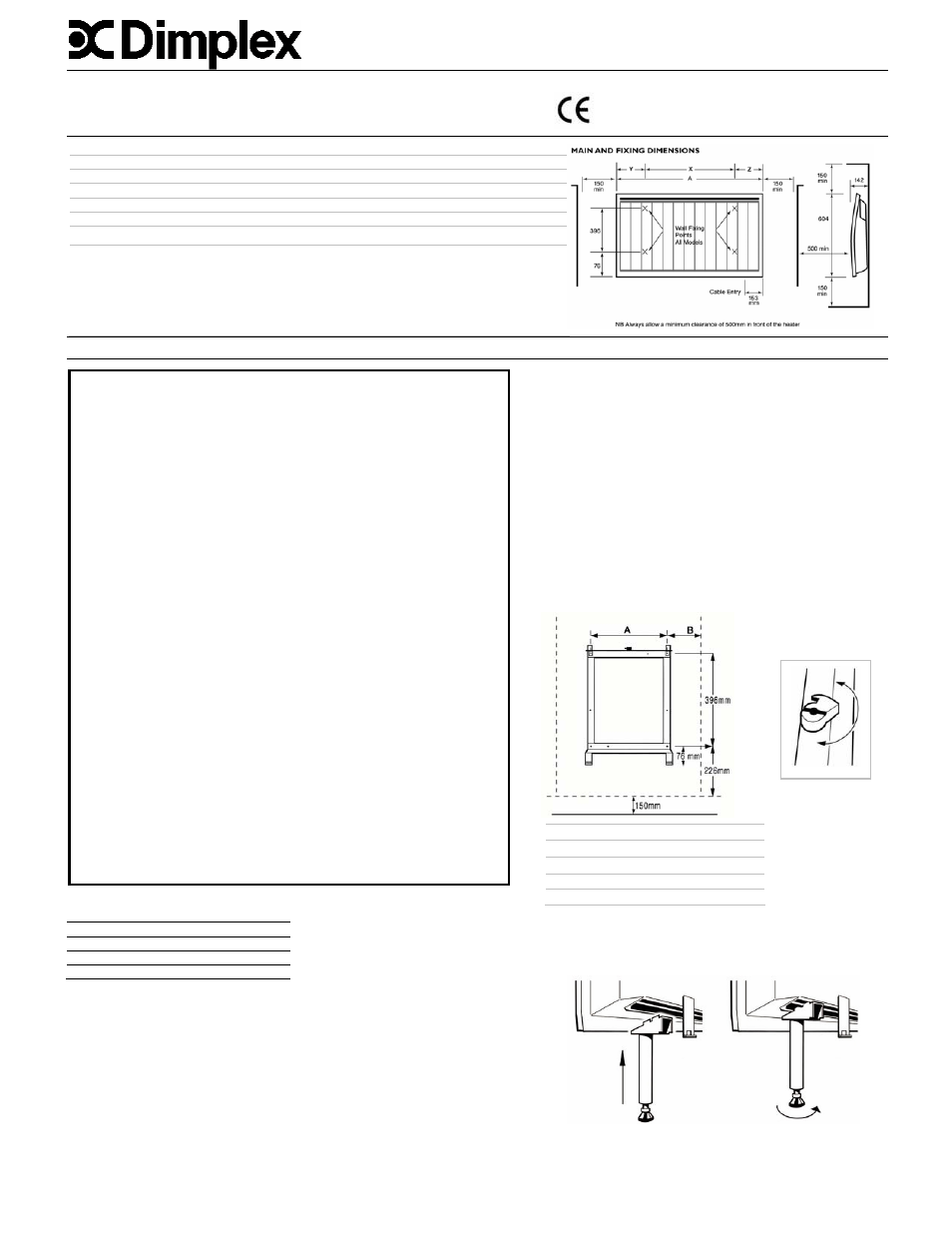
Dimensions and Specification
Model Loading Length
(A) Height Depth X
Y
Z Weight
(kW) (mm)
(mm)
(mm)
(mm)
(mm)
(mm)
(kg)
CAL075 0.75
455
604 142 140 87 228 17
CAL100 1.0
621 604 142 300 87 234 24
CAL150 1.5
870 604 142 400 226 242 33
CAL200 2.0
1202 604 142 700 227 275 47
THESE INSTRUCTIONS SHOULD BE READ CAREFULLY AND RETAINED FOR FUTURE REFERENCE
Installation and Operating Instructions
Wall Mounting / Installation
The heater should be positioned observing the minimum clearances
stated around the heater.
(see also ‘Electrical’ section)
The wall bracket supplied with the heater must be used
1. Using a screwdriver, turn the latch in a clockwise direction to
unlatch the bracket, then remove it from the appliance (see Fig.1)
2. Mount the bracket on the wall using a minimum of 4 screws
(max diameter 6mm) making sure that it is the correct way up and
at the correct height. (see Fig.2)
3. Position the appliance on the bracket.
4. Re-latch the bracket turning the latch anti-clockwise.
Electrical
The wires in the mains lead are coloured in accordance with the following code:
GREEN & YELLOW EARTH
BLUE NEUTRAL
BROWN LIVE
BLACK PILOT
WIRE
(See also ‘Pilot Wire Connection’)
The heater is fitted with a length of flexible cable for connection to the fixed wiring of the
premises through a suitable connection box positioned adjacent to the heater.
The supply circuit to each heater must incorporate a double pole isolating switch having a
contact separation of at least 3mm
Pilot Wire Connection
The BLACK control wire is designed to carry a signal from slot in or wall mounted Dimplex
programmers. If, however a programmer is not being used, the pilot wire should be isolated in
accordance with the current IEE Wiring Regulations.
IMPORTANT - Do NOT connect the BLACK pilot wire to earth
Care should be taken with the installation of the pilot wire(s) as when switching to background
(set back) they become energised at 240V although only at a current of 1mA.
In every case a suitable means of isolation must be provided for the pilot wire and marked to
indicate that two sources of supply may be present at the heater.
Where pilot wires are installed separately from the heater final sub-circuit they should be
protected, double insulated and carry their own integral earth continuity conductor.
Model A
(mm B
(mm)
CAL075 140
228
CAL100 300
234
CAL150 400
242
CAL200 700
27
IP24
Issue 5 November 2004
General
The Calidou radiator is designed to provide exceptional levels
of comfort with a combination of radiant and convected heat
in both domestic and commercial applications.
IMPORTANT SAFETY ADVICE
•
When using electrical appliances, basic precautions should always
be followed to reduce the risk of fire, electrical shock, and injury to
persons, including the following:
•
WARNING THE SURFACES OF THIS HEATER CAN BE HOT
Momentary contact with any part of the heater should not cause
injury. However, aged or infirm persons or young children should not
be left unsupervised in the vicinity of the heater unless a suitable
guard is fitted
•
IMPORTANT – If this heater is installed in a room containing a bath or
shower, it should be so installed that switches and other controls
cannot be touched by a person using a bath or shower – to comply
with this requirement see ‘Lock the Control Cover’ section on page 2.
•
If you use this heater in conjunction with an external thermal control,
a programme controller, a timer or any other device which switches
the heat on automatically, observe all safety warnings AT ALL TIMES
since a fire risk exists when the heater is accidentally covered or
displaced
•
The installation of this product should be carried out by an electrician
or competent person and be in strict accordance with the current IEE
Wiring Regulations and relevant Building Regulations
•
This heater must not be mounted within 150mm of curtains and other
combustible materials or 100mm from a shelf or overhang
•
NEVER cover or obstruct in any way the heat outlet slots at the top of
the heater or the air inlet slots at the base of the heater
•
DO NOT cover the heater – Do not place material or garments on the
heater or obstruct the air circulation around the heater
•
Before connecting the heater check that the supply voltage is the
same as that stated on the heater
•
The heater must be installed in accordance with these instructions
•
The heater must be mounted using the wall bracket supplied. The
heater should only be operated in the upright position
•
The heater should be positioned in accordance to the clearances
stated in these instructions
•
DO NOT locate this heater immediately beneath a fixed socket outlet
Fig.1
Fig. 2
If the wall is a light partition or crumbling, then supporting legs
are also needed
(Part No. CAL0001). The heater MUST be fitted to the wall as
well as having the supporting legs
1.
Place the legs under the heater
2.
Position the hinges into the grooves in the air inlet
3.
Unscrew the jacks, until they reach the floor