Hardware installation – DSC POWERSERIES PC1616 User Manual
Page 2
Hardware Installation
Begin the installation by mounting the cabinet in a dry protected area with access to unswitched AC power.
Install Hardware in the sequence indicated below. Do NOT apply power until installation is complete.
NOTE: All wiring entry points are designated by arrows. All circuits are classified UL power limited except for the battery leads.
Minimum 1/4” (6.4mm) separation must be maintained at all points between power limited and non-power limited wiring and
connections.
1. Keybus Wiring
The 4-wire KEYBUS (red, black, yellow and green) is the communication connection between the control panel and all modules. The 4 KEY-
BUS terminals of all modules must be connected to the 4 KEYBUS terminals of the main control panel.
The following rules must be followed when wiring the Keybus:
•
Minimum 22 AWG wire, maximum 18 AWG (2-wire twisted pre-
ferred
•
Do NOT use shielded wire
•
Modules can be home run, connected in series or can be T-
tapped provided that the maximum wire distance from the control
panel to any module does not exceed 1,000 feet (305m)
•
No more than 3,000 feet (915m) of wire can be used in total
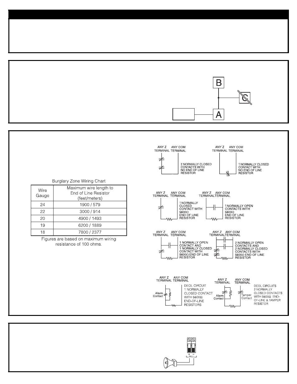
2. Zone Wiring
Zones can be wired for Normally Open, Normally Closed Contacts
with Single-end-of-line (SEOL) resistors or Double End-of-Line
(DEOL) resistors. Observe the following guidelines
•
For UL Listed Installations use SEOL or DEOL only.
•
Minimum 22 AWG wire, maximum 18 AWG
•
Do NOT use shielded wire
•
Wire run resistance shall not exceed 100
Ω.
Refer to the chart
below.
•
Section [001-004] Selects Zone Definition
•
Section [013] Opt [1] Selects Normally Closed or EOL resistors
•
Section [013] Opt [2] Selects Single EOL or Double EOL resis-
tors.
Zone Status
Loop Resistance
- 0
Ω (shorted wire/loop)
- 5600
Ω (contact closed)
- infinite (broken wire, open)
- 11,200
Ω (contact open)
Loop Status
Fault
Secure
Tamper
Violated
3. Bell Wiring
These terminals supply 700mA of current at 12V
DC
for commercial
installations and 11.1-12.6 V
DC
for residential installations (e.g.DSC
SD-15 WULF). To comply with NFPA 72 Temporal Three Pattern
requirements:
Program Section [013] Opt [8] ON.
The Bell output is supervised and power limited. If unused, connect a
1000
Ω resistor across Bell+ and Bell- to prevent the panel from dis-
playing a trouble. See [
✱][2].
NOTE: Bell output is current lim-
ited by 2A PTC
NOTE: Steady, Pulsed and Tem-
poral Three Pattern alarms are
supported.
CONTROL
PANEL
150’ (46m)
150’ (46m)
500’ (152m)
500’ (152m)
Normally Closed Loops - Do NOT use for UL Installations
Single End-of-Line Resistor Wiring
Double End-of-Line Resistor Wiring
OBSERVE
POLARITY
BELL/SIREN
700mA (max.)