Pilot, V. charging the system with water – Bryant 451A User Manual
Page 7
Attention! The text in this document has been recognized automatically. To view the original document, you can use the "Original mode".
A wrench-type shut-off valve should be installed
in the gas line within sight of, and convenient to,
the 451. Provide a ground joint union upstream of
the combination regular shut-off, and preferably
outside the unit.
Install a drip leg trap in the gas supply riser lead
ing to the unit. After gas pipe connections have
been made, purge the lines and check for leakage.
Use a soap and water solution or other such mater
ial.
Never use matches, candles, flame or other source
of ignition to check leakage.
PILOT
Light the pilot using the procedure outlined on the
Lighting Instruction Plate attached to generator.
The pilot flame should be soft blue in color. The
flame should be of sufficient length to provide good
impingment on the unimetal element of the Bryant
pilot. Flame should extend upward between the
carry-over ports of the two adjacent burners.
If the pilot flame does not have the appearance
described above, it may be adjusted by means of
the manual pilot shut-off valve which is equipped
with an adjustable screw. Turn the handle to the
full-open position and remove the screw cap on the
valve handle, thus exposing the adjustable screw.
Turn adjusting screw until flame has the desired
appearance. Replace screw cap.
V. CHARGING THE SYSTEM WITH WATER
Caution: Do not run the pump
dry. Freezing condL
tions will not damage the pump; however, do not
attempt to operate the pump when chiller or chilled
water lines are frozen.
1. Turn off main manual gas shut-off valve.
2. Remove the filler cap from water chiller tank.
3.
Disconnect line at chiller inlet. (When install
ing the chilled water lines, it is advisable to leave
this connection open until lines have been flushed).
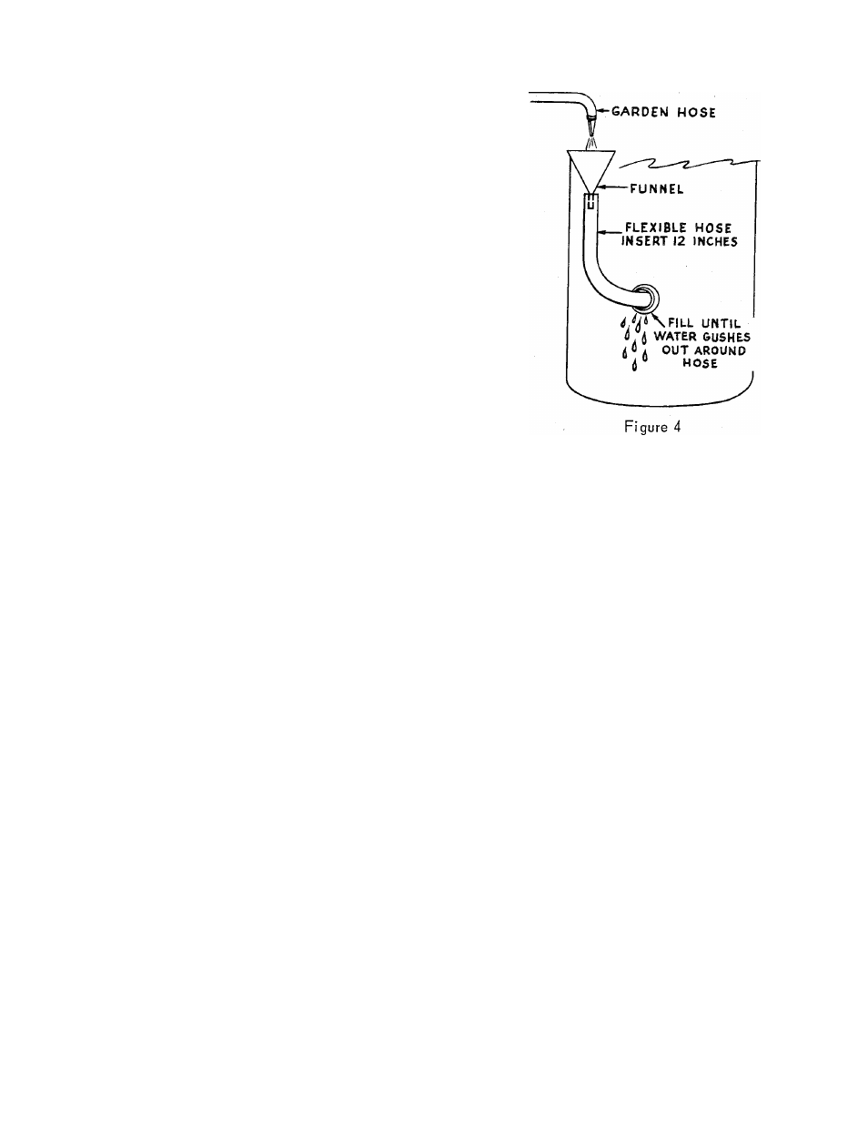
4.
Fill the tank with tap water by inserting a
garden hose into the filler tube about 12 inches
and running water into the chiller until it gushes
out around the hose. See Figure 4.
5.
Start pump. Allow pump to operate until all
foreign matter has been flushed from the pipes.
Continue to supply water to the tank during this
cleaning period.
Note: If water does not circulate when the pump
is started, air may be trapped in the pump. Bleed
the air from pump through the 1/8" slotted head
bleed valve located on top of the pump discharge.
Open valve with screw driver. Close valve when
the trapped air is removed and water appears.
6. Turn off pump and hose. Make pipe connection
to chiller inlet.
7.
Turn on hose and fill tank until water gushes
out around hose. Remove hose and replace filler
cap.
8. Start pump and while water is circulating, check
for leaks throughout the chilled water system.
9. Stop pump and remove filler cap. Insert one end
of a piece of water hose into the tank at least 12".
Insert a clean plastic or metal funnel in the other
end of the hose.
10. Start pump and pour carton of borax into funnel.
Flush borax into chiller with water from water
hose used for filling until tank over-flows. Remove
hose and replace filler cap. The package of borax
supplied is sufficient for chilled water systems
containing up to 20 gallons of water. For systems
- 5-
EH 451