B. pipe length and diameter – Bryant 451A User Manual
Page 3
Attention! The text in this document has been recognized automatically. To view the original document, you can use the "Original mode".
TABLE
Nominal
Pipe Size
Inches
Allowable Distance* between Coil and Chiller
Polyethy ene Pipe
Copper Pipe
Galvanized Pipe
Size 36
Size 54
Size 36
Size 54
Size 36
Size 54
3/4
40'
—
35'
—
25'
—
1
150'
45'
140'
40'
90'
30 '
1-1/4
530'
145'
360'
100'
370'
90'
* Note: Values shown in above table are for one direction only. The total length of pipe from chiller to coil
and return would be double the above table values. The above table applies to single unit installations only.
Figure 1
II. CONNECT CHILLED WATER LINES
A.
MATERIALS
Refer to section on “Cold Weather Protection” at
the end of this instruction.
1. Piping
a. Polyethylene Plastic Pipe - use medium density
flexible pipe whose wall thickness approximates
Schedule 40 pipe (Commercial Standard CS 197-60).
Pipe must be virgin plastic. Do not use pipe manu
factured from re-claimed plastic.
□
AVOID
OPEN
WINDOWS
SLEEPING
QUARTERS
□
AVOID
'
e l l s
"
GARAGE
LIVING
AREA
□
GOOD
LOCATION
Figure 3
b. Copper - satisfactory substitute.
c. Galvanized - satisfactory substitute.
2. Fittings
a. Nylon - use when possible.
b. Brass - satisfactory substitute.
c. Galvanized - satisfactory substitute.
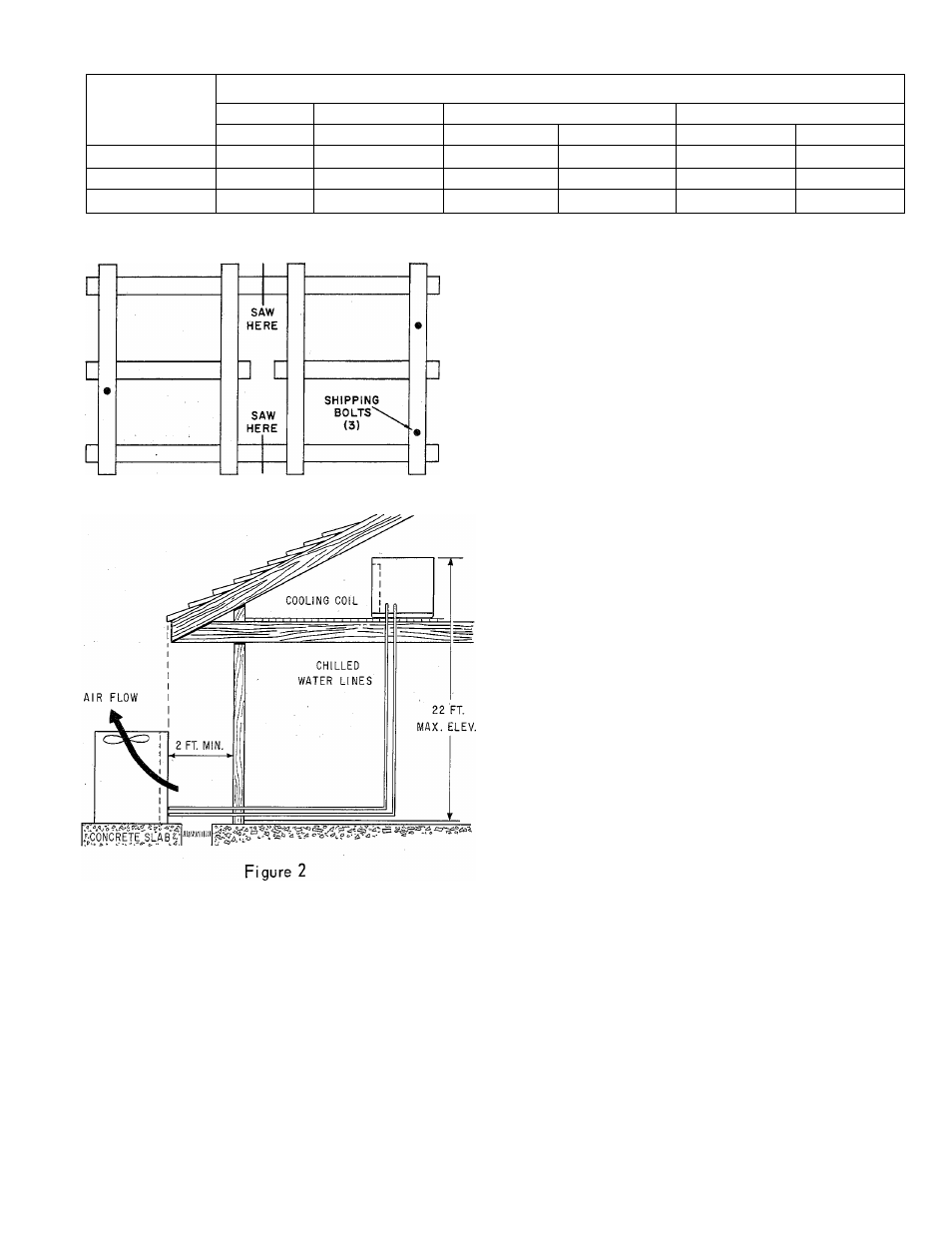
B. PIPE LENGTH AND DIAMETER
Table I shows maximum length of pipe of different
diameters that can be used between the pump dis
charge and the coil inlet and still maintain mini
mum allowable (design) water flow rate.
1. Multiply table values by two to obtain the total
length of pipe from chiller to coil ond return.
2.
Length is measured along the pipe path and
therefore includes vertical distance between the
water coil and the chiller.
3. Lengths shown in Table I are based on using a
total of eight elbows in the entire water line
(chiller to coil and return). Lengths are predicated
on the use of a Bryant matching water coil. For
greater distances use larger pipe or add a pump.
- 3 -
EH 451