Altec Lansing 1590E User Manual
Page 2
Attention! The text in this document has been recognized automatically. To view the original document, you can use the "Original mode".
CONDUIT
. KNOCKOUTS
FOR SPEAKER
WIRING
TRANSFORMER
ACCESSORY
RECEPTACLE
The input leads are connected to terminals
3 and 4 of the INPUT terminal board (see
Figure 4).
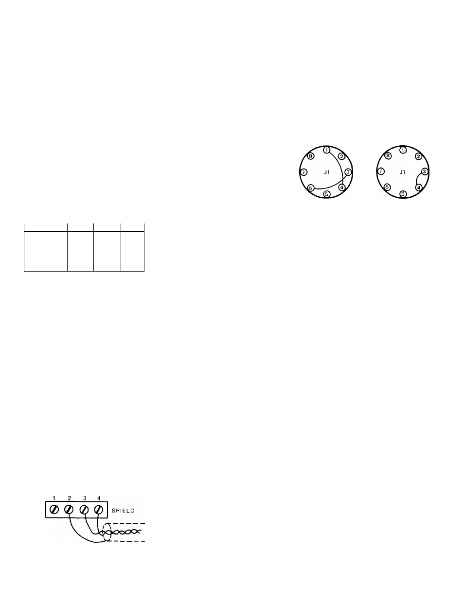
When shipped from the factory, pins 3 and 4
of J1 are strapped together to provide a
600-ohm Input. A 150-ohm Input may be
obtained by removing the strap from pins 3
and 4 and then strapping pin 1 to 4, and
strapping pin 3 to 6 (see Figure 5).
Both the direct and transformer Isolated
inputs may be used simultaneously If Isola
tion resistors are Installed In either or both
input lines, to prevent one Input source
from short circuiting to the other.
150 ÍÍ WIRING
600Í2 WIRING
I
I
VOLTAGE
' _
RATING BATTERY
NAMEPLATE TERMINAL
BOARD
BATTERY
FUSE
HEAT SINK
SHROUD
FILTER
SWITCH
INPUT
TERMINAL
BOARD
Figure 2. Rear View of 1590 Power Amplifier
Terminal Block TB8/TB9 Connections
Transformer T1
Wire Color
100 V
120 V
240V
Brown
TB9-4
TB8-4
TB8-4
White
TB8-4
TB9-4
TB9-2
Black
TB9-7
TB9-7
TB9-5
White-Brown
TB9-1
TB8-3
TB9-4
White-Black
TB9-8
TB9-8
TB9-8
Permanent AC Power Connections*
Pilot Light S2-4
AC Cord (black)
AC Cord (white)
Switch SW2-3
Fuse FI-2
Capacitor C7
Capacitor C6
TB9-6
TB8-9
TB9-9
TB8-5
TB8-8
TB9-10
TB8-10
*Do not make any wiring changes of
these wire connections when altering
the amplifier for different primary
power operating voltage.
Figure 3. Primary Power Conversion Chart
for 100V, 120V, and 240V 50/60 Hz Operation
4. Select the appropriate voltage rating
label from the rating label strip supplied
with the amplifier. Affix label over pre
vious
voltage
rating
designation
on
chassis. See Figure 2.
5. When 1590 is strapped for 200V or 240V
line power, replace front panel fuse (FI)
with 2A, 250V, slo-blo type fuse.
6. Close front panel and secure with four
screws previously removed.
Battery Connections
If desired, the 1590 may be connected to an
external 24/28 volt battery with minus (-)
as ground. Terminals for the dc power con
nections are on TB4 (see Figure 2). If ac
power fails, transfer to dc power Is instan
taneous, autoamtic and silent. The battery
ower supply Is not operated by the primary
power ON-OFF switch on the front panel. If
switching of battery power Is desired, an
external relay or switch should be provided
by the user.
Input Connections
Input connections may be either direct or
transformer-isolated at the INPUT terminal
board (TB1) (see Figure 2). Direct coupling
Is accomplished by connecting the Input
leads (shielded conductor recommended)
to terminals 1 and 2. Terminal 2 Is ground
(see Figure 4).
For transformer-isolated input, a plug-in
15095A or 15335A Line Transformer must be
plugged into receptacle J1 (see Figure 2).
INPUT
0
0
SHIELD
INPUT
DIRECT CONNECTION
1. For unbalanced high-impedance sources.
2. For bridging unbalanced low-impedance
lines having signal voltages of 0.8V rms
or higher.
TRANSFORMER ISOLATED CONNECTION
1. For balanced or unbalanced lines of 150
or 600 ohms* up to level of
+
15 dBm
(with 15095A Line Transformer),
2. For low-impedance line bridging input or
15,000 ohm line-matching input (with
15335A Line Transformer),
'Factory wiring at receptacle J1 Is for 600
ohms (see Figure 5).
Figure 5. Wiring of Transformer Accessory
Receptacle for Input Impedance of 150 or
600 Ohms. Factory Wiring Is for 600 Ohms
Output Connections
Output transformer taps provide connec
tions tor 25V (140 watts), 30V, 70.7V, 100V,
140V and 200V distribution systems. Class I
wiring must be used for 100V, 140V and
200V systems. Class II wiring may be used
only for the 30V and 70V systems. Connec
tions are made at terminal board TB2
located within the chassis (see Figure 6).
Wiring from the speaker system feeds
through the chassis to TB2;
Vi"
conduit
knockouts In the chassis provide access to
output terminals of TB2 and permit termina
tion as required for Class I wiring (see Fig
ure 2).
Recommended wire size for 200V operation
is 18 gauge (solid or stranded), for which
power loss Is V
2
dB per 1900 feet of paired
wire. When rigid conduit is not used clamp-
type cable connectors must be Installed in
the conduit knockouts to secure the cable
and provide strain relief.
NOTE-
Typical clamp-type cable connectors
are the Appleton CG-1850 (for Class I
flexible cord such as type SV or SVT),
and the Appleton CG-1250 (for Class
II audio cable usch as Alpha Wire
Corp. No. 1897 [stranded] or No. 1797
[solid]).
Figure 4. Input Connections
After speaker distribution wires are passed
to the site of TB2, quick-connect terminal
clips (T&B type RA257) must be installed.
Be sure that output wiring between knock
outs and TB2 does not exceed 9 Inches In
length. Strip
'/*"
Insulation from the wire
ends and install the terminal clips. Twist
stranded wire to assure that all strands
properly enter the sleeve of the terminal
clip. Use an appropriate crimping tool (such
as M. Klein & Sons #1002) to crimp the
terminal clips to the wire ends.
Connect terminal clips to the terminals of
TB2 which have the desired Impedance. If
total speaker system Impedance falls be
tween two rated output values of the 1590,
- 2 -