Assembly – Bolens 117-030A User Manual
Page 3
Attention! The text in this document has been recognized automatically. To view the original document, you can use the "Original mode".
ASSEMBLY
Your new mower is shipped completely assem
bled with the exception of the handle.
1. Remove lawn mower and all parts from
carton. Make certain that all loose parts and
literature are removed from carton before
carton is discarded.
2. Extend throttle control assembly, which is
attached to rear of mower and place on floor.
^CAUTION
Do not bend or kink control wire.
NOTE
Some engines have manual friction
control on the engine; these require
no remote throttle control.
3. a. Snap lower handle into position on two
lugs which extend from either side on the
rear of the deck.
b. Assemble the two upper handle parts with
cap screws and locknuts provided in parts
bag. The yellow cap screw should be used
to attach throttle control assembly to
upper handle as shown in diagram. Do not
tighten nuts.
c. Attach upper handle assembly to lower
handle with cap screws and locknuts.
Tighten all nuts.
d. Secure control wire to lower handle with
cable clips.
4. Check all nuts and bolts for correct tightness.
5. Slip hand grips on the upper end of each
handle. They will slip on more easily PF you
first soak them in warm soapy water.
Chute Deflector
Shipping Block to be Removed
NOTE
It may be necessary to bend the
ends of the lower handle inward
slightly to assure a snug fit against
the deck mounting area.
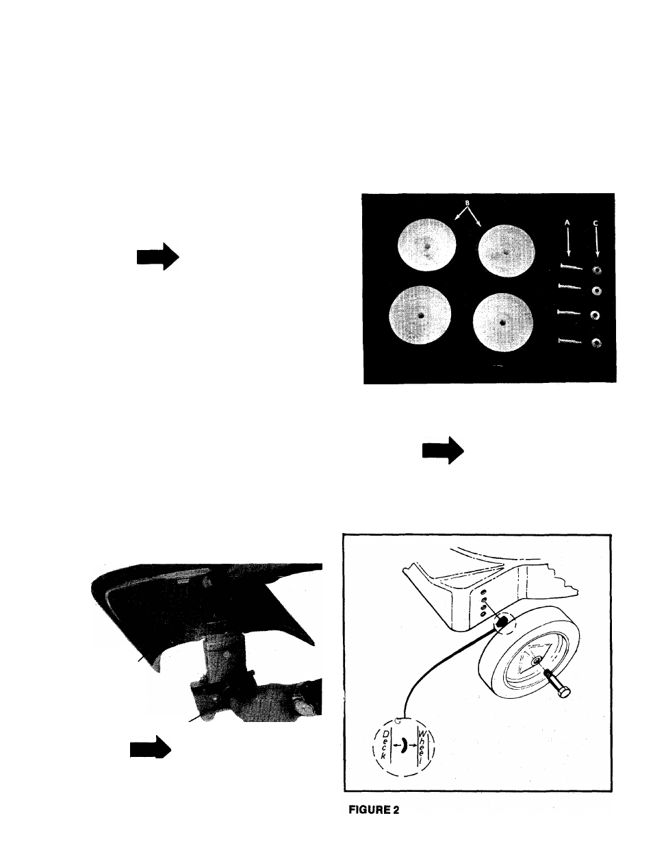
6. Place shoulder bolt (A) through wheel (B). See
figure 1.
7. Place crown side of belleville washer (c)
towards the wheel (away from deck). See
figure 2.
8. Using a
W
wrench secure wheel to deck.
FIGURE 1
NOTE
Tighten shoulder bolt enough to
slightly
compress
the
belleville
washer.
DO NOT COMPLETELY compress
washer.