Control box's, 597saci – Bryant 108-451 User Manual
Page 9
Attention! The text in this document has been recognized automatically. To view the original document, you can use the "Original mode".
CONTROL BOX'S'
BLUE
BROWN
YELLOW
HIGH
PRESS.
CUTOUT
m
BLACK
BROWN
X
Y
G
R
1 •
1»
( »
1
f
\
HIGH TEMP.
CUTOUT
o
YELLOW
0
BLACK
/
GAS
VALVE
--------------------y-----------------
TO CONTROL BOX NO. A
BLUE
GAS PRESSURE
SWITCH
REIGNITION
PILOT SWITCH
FACTORY LINE VOLTAGE
FACTORY LOW VOLTAGE '
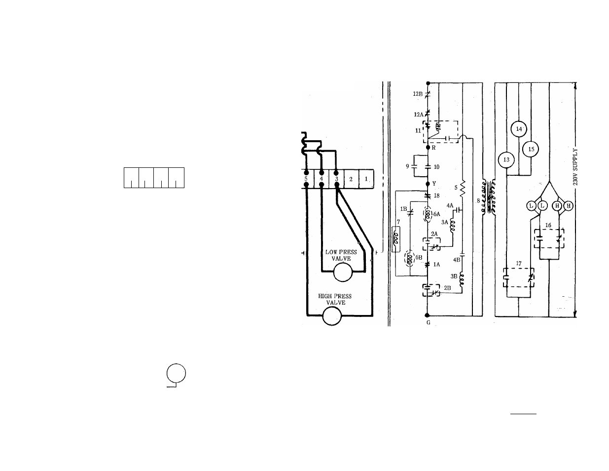
SCHEMATIC WIRING DIAGRAM
X
OF 108-451
1. PRESSURE SWITCHES
2. PILOT
3. GLOW COIL
4. GAS PRESS. SW.
5. RESISTOR
6. GAS VALVE
7. POWER RELAY COIL
8. TRANSFORMER
10
.
11
.
12
.
13.
14.
15.
16.
17.
THERMOSTAT
HI-TEMP RELAY
HI-TEMP CUTOUT
FAN MOTOR
PUMP MOTOR
TIMER MOTOR
TIMER SWITCH
POWER RELAY
9. THERMOSTAT OVERRIDE SW. 18. PART LOAD CONTROL
597saci
o
00
Figure 4 - Unit Wiring Natural Gas - Control Box B
With Re ignition
- EVOLUTION 577D----A (40 pages)
- Packaged Air Handling Units 542J (4 pages)
- Air Handling Units 524J (36 pages)
- 591B (12 pages)
- Electric Air Conditoner 597C (28 pages)
- 599C (2 pages)
- PREFERREDT A07044 (80 pages)
- 502A (8 pages)
- 564A (20 pages)
- 702B (28 pages)
- 538J-18-1 (12 pages)
- 764A (24 pages)
- 580J*04--12 (73 pages)
- AIR CONDITIONERS 564A (20 pages)
- 561G (2 pages)
- PURON PLUS 598B (40 pages)
- R-410A 583B (30 pages)
- 538MNQ (10 pages)
- EVOLUTION 707D (4 pages)
- 463AAC008BA (19 pages)
- DURAPACK 558F (70 pages)
- 664A (4 pages)
- 479 D (13 pages)
- 569D (84 pages)
- Legacy Air Conditoner H3A (6 pages)
- 561S (2 pages)
- R-22 561G (6 pages)
- 594D (24 pages)
- 450D (10 pages)
- 574D (32 pages)
- DE LUXE 12 SEER 552A (36 pages)
- R-22 (52 pages)
- CD5A (8 pages)
- 564B (20 pages)
- Air Conditeners 180A (16 pages)
- 677C--A (36 pages)
- 559F (48 pages)
- LEGACY 564B (4 pages)
- s 123A (6 pages)
- 598A (8 pages)
- Air Cooled Condensing Units 569C (20 pages)
- 580J*08--14D (85 pages)
- Electric 594D (24 pages)
- 588A (28 pages)
- 577C (8 pages)