B. pipe length and diameter, C. insulation, D. height of coil above absorption unit – Bryant 108-451 User Manual
Page 3: E. water coil connections
Attention! The text in this document has been recognized automatically. To view the original document, you can use the "Original mode".
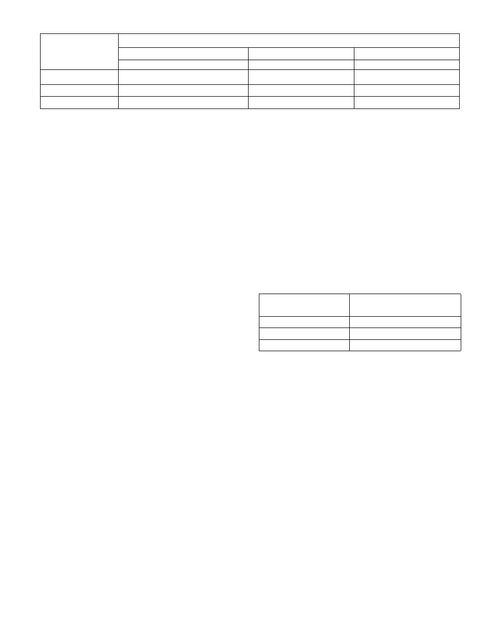
Table I
Nominal
Pipe Size
Inches
Allowable Distance* Between Coil and Chiller
Polyethylene Pipe
Copper Pipe
Galvanized Pipe
Size 108
Size 108
Size 108
1
48'
67'
72'
IV
a
272'
210'
285'
IV
2
610'
492'
642'
* Note: Values shown in above table are for one direction only. The total length of pipe from chiller to coil
and return would be double the above table values. The above table applies to single unit installations only.
B. PIPE LENGTH AND DIAMETER
Table I shows maximum length of pipe of different
diameters that can be used between the pump dis
charge and the coil inlet and still maintain mini-,
mum allowable (design) water flow rate.
1. Multiply table values by two to obtain the total
length of pipe from chiller to coil
and
return.
2.
Length is measured along the pipe path and
therefore includes vertical distance between the
water coil and the chiller.
3. Lengths shown in Table I are based on using a
total of eight elbows in the entire water line (chil
ler to coil and return). Lengths are predicated on the
use of a Bryant matching water coil. For greater
distances use larger pipe or add a pump.
C. INSULATION
1. Insulate supply and return lines separately.
2. Material should be of good quality and be covered
with a good vapor barrier. Armaflex or equivalent is
recommended.
Wall thickness:
1/2'' wall thickness - south of 40° N. latitude
3/8" wall thickness - north of 40° N. latitude
D. HEIGHT OF COIL
ABOVE ABSORPTION UNIT
Maximum vertical distance from chiller outlet to
top
of coil is 49 feet. For greater heights, a greater
pumping head is required. Increasing the pipe size
will not help.
E. WATER COIL CONNECTIONS
1. If cooling coil is used in connection with heat
ing unit, install cooling coil in parallel with or
downstream of heating unit to avoid condensation in
the heating unit.
2. If coil is located in warm air stream, do not
connect polyethylene pipe directly to coil. Connect
a minimum of 24 inches copper or galvanized pipe
to both the coil inlet and outlet. Then connect the
plastic pipe to these nipples.
3. On installations where the outside piping freezes
and the coil is in a heated air stream, precautions
must be taken to provide for water expansion. The
connecting polyethylene plastic pipe acts as an
expansion vessel if there is enough footage of this
pipe in the heated space (space not subject to
freezing). The following table shows the minimum
lengths (total inlet and outlet) of plastic piping of
various diameters that are required for both sizes
of coils to provide adequate expansion volume.
Nominal Pipe Size
Inches
Length of Plastic Pipe
in Feet
1
70
VA
40
IV
2
29
If the total plastic chilled water line footage in the
heated space is not as long as the minimum values
shown in the table, tee a vertical pipe of sufficient
volume into either of the coil connections to provide
for expansion, or the line should be drained.
III. ELECTRIC CONNECTIONS
1. Make all electric connections in accordance with
the National Electrical Code and any local ordi
nances or codes that might apply.
2.
Provide a separate power supply for the air
conditioner.
3. Provide a fused disconnect switch within sight
of and not more than 50 feet from the absorption
unit. Use 35 amp standard fuse.
4. The absorption unit is shipped fully wired from
the factory. Connection of 230V power and low volt
age connection to the thermostat control are re
quired in the field. Before proceeding, inspect
factory wiring for loose connections which may have
resulted during shipment.
- 3 -
108/451