Bryant 450D User Manual
Page 9
Attention! The text in this document has been recognized automatically. To view the original document, you can use the "Original mode".
?. CHAliGING THE SYSTEM WITH WATER
VI. CHECK-OUT AND OPERATION
Caution:
Do not ran the pump dry. Freezing conditions
will not damage the pump, but do not attempt to operate
pump when chiller or chilled water lines are frozen.
1. Remove belt from condenser fan.
2. Turn off main manual gas shut-off valve.
3.
Remove top cover from water chiller tank. Remove
container of chilled water additive stored in tank.
4.
Fill tank with tap water until distribution pan at top
is covered with water. A garden hose is useful for this
operation.
5.
Disconnect line at chiller inlet. (When installing the
chilled water lines, it is advisable to leave this con
nection open until lines have been flushed). Start pump.
Allow pump to operate until all foreign matter has been
flushed from the pipes.
It is recommended that the gar
den hose be used to supply water continuously to the
tank during this cleaning period.
6. Turn off pump. Make pipe connection to chiller inlet.
7.
Refill the chiller tank with tap water and remove
garden hose.
8.
Start pump and, while water is circulating, check for
leaks throughout the chilled water system.
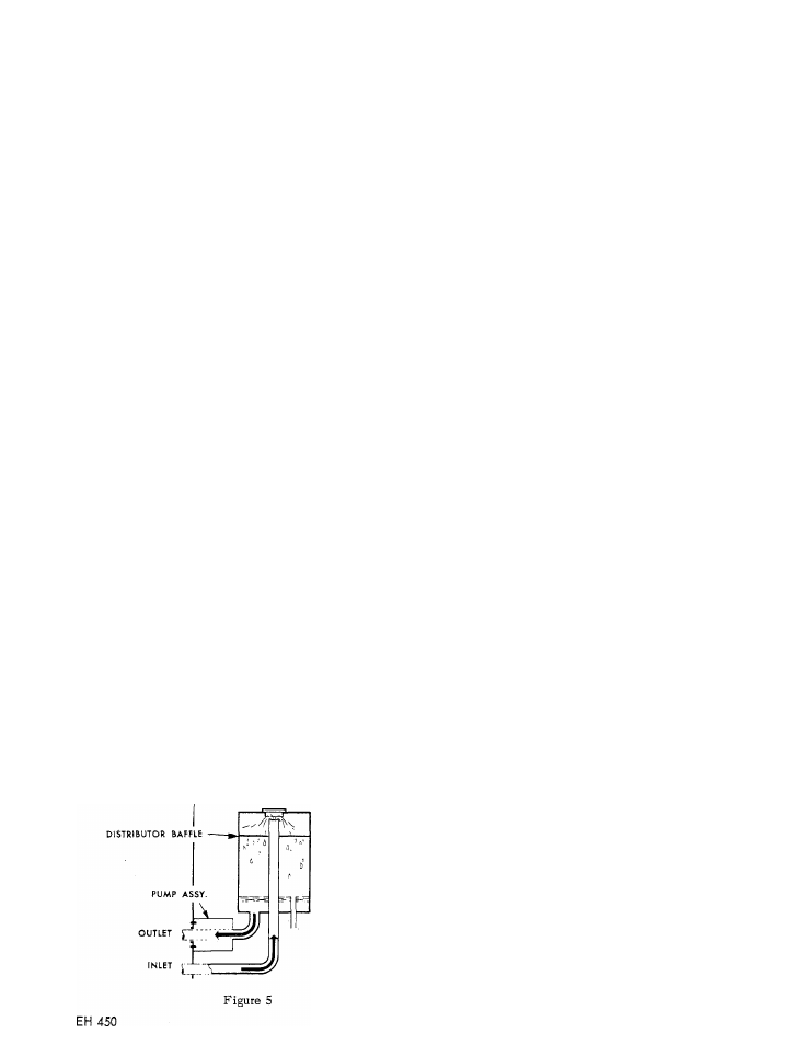
9. Adjust the water level in the chiller while the pump
is still running. This is accomplished by removing the
water level pipe cap as shown in Figure 5. When water
ceases to drain, the level is properly adjusted. Replace
the drain cap. Turn off the pump. (If no water flows
when the drain cap is removed, refill the tank and repeat
the draining operation to adjust the water level).
10.
Add chilled water additive (packed in chiller tank).
The
package
supplied
is
sufficient
for
chilled
water
systems
containing
up
to
20
gallons
of
water.
For
systems
larger
than
20
gallon
capacity,
add
one-half
(1/2) package for each additional 10 gallon capacity or
fraction thereof. (Consult Bryant distributor for estimat
ing chilled water circuit capacities).
11. Replace the lid on the chiller tank.
12. Replace the condenser fan belt. Adjust tension.
13. The system is now ready to operate.
OPERATING LEVEL
DRAIN
1.
Be sure the condenser fan guard has been installed
properly.
2.
Be sure main manual gas valve is off. Light pilot as
described on instruction plate.
3.
Set thermostat to “Cool”; set thermostat fan switch
to “Auto”; and set thermostat below room temperature.
4. Turn on main electric switch to unit.
5.
Observe condenser fan operation; adjust belt tension
if necessary.
6.
Check indoor fan operation by turning thermostat fan
switch
to
“on”
for
continuous
fan
operation.
Move
thermostat above room temperature and observe that the
indoor fan remains on.
7.
To place the system in operation, open the main
manual gas valve, replace the front panel (all panels),
and set the thermostat at the desired temperature.
High Temperature Cut-Out. The high temperature circuit
includes
a
high
temperature
control
located
on
right
side of generator plus a high temperature relay (lockout
relay) located in control box. If the generator becomes
overheated the contacts in the high temp control open,
causing the high temp relay to go into lockout position.
The
gas
valve
closes,
the
fans
and
pump
stop,
and
they will not recycle until the lockout relay is reset.
To reset lockout relay turn electric power off and then
back on. Be sure to locate and correct cause for high
temp cut-out.
VII. ADJUST GAS INPUT
Gas input should agree with that shown on the rating
plate of the unit. The burners are equipped with fixed
orifices intended to give the correct gas input with a
manifold pressure of 2.6" w.c., using 1030 BTU natural
gas of 0.63 S. G. Before lighting burners, inspect to be
sure that they have not become dislodged or cocked
during shipment and installation.
To measure gas input, proceed as follows:
1. Adjust primary air if necessary.
2. Measure the- gas input at the meter. Be sure all
other gas appliances are turned off. Input at the
burner's
may
be
increased
or
decreased
slightly
by
adjustment
of
the
regulator
in
the
burner
supply line.
Caution:
Prolonged operation of the unit should not be
attempted with the front panel off. The unit may be ran
for short periods with the panel removed.
- 7 -