Ahaching the brake cable, Securing the cables (hardware d), Attaching the starter rope (hardware b) – Bolens 111-051R372 User Manual
Page 6: Installation of wheels (hardware e)
Attention! The text in this document has been recognized automatically. To view the original document, you can use the "Original mode".
‘Z” Fitting
Biade
Controi
Handle
FIGURE 3.
Hole in
Bracket
Plastic Fitting
FIGURE 5.
AHACHING THE BRAKE CABLE
1. The brake cable is attached to the engine, and has a “Z”
fitting on the loose end. Route the brake cable below the
lower handle. Place end of cable through the hole in the
-bracket as shown in figure 3. Be careful not to bend or
kink the cable at any time. Push the plastic fitting until
it locks into the hole in the bracket.
A
WARNING: Brake cable must be assembled as
shown for proper blade brake operation.
2. Hook the “Z” end of the brake cable into the hole in the
blade control handle from the inside to the outside as
shown in figure 3.
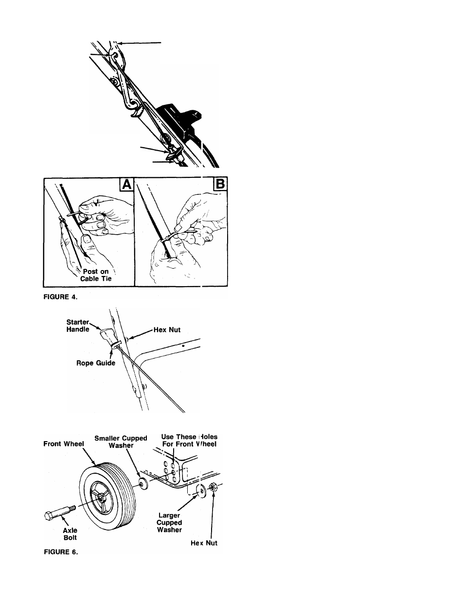
SECURING THE CABLES (Hardware D)
Secure the cables to the left side of the handle as follows.
A
WARNING: When attaching the control cables,
the cables must be routed to avoid contact with
all sharp edges and hot surfaces to prevent
damage to the cables, which will render the con
trols inoperative.
1.
Insert posts on cable ties into holes provided on the in
side of the handle, one on the upper handle and two on
the lower handle. The holes may be either on the inside
--------or outside of the handles. See figure 4A.
2. Secure the cable(s) with the cable ties. See figure 4B.
3. Trim excess ends of cable ties.
ATTACHING THE STARTER ROPE (Hardware B)
1. The starter rope is inside the top of the engine. Additional
rope may be wound around the starter handle. If so, un
wind the rope from the handle.
2. With the spark plug wire disconnected and grounded,
depress the blade control handle and pull the rope out
of the engine.
—3. Place the rope guide around the starter handle, so the
rope guide is positioned as shown (bends downward
slightly). Insert the rope guide into the handle, and secure
with hex lock nut.
INSTALLATION OF WHEELS (Hardware E)
The three holes provide three cutting heights for your mower.
Use the same hole location for all four wheels when assem
bling. If wheels are to be assembled in the lowest cutting posi
tion (highest hole in the deck), refer to the note below.
If your mower has two sets of holes (see figure 6), the front
wheels must be assembled in one of the three holes nearest
the front of the deck. The rear wheels must be assembled
in one of the three holes nearest the rear of the deck.
-To assemble the wheels: (See figure 6)
1. Place axle bolt through wheel.
2. Place one smaller cupped washer on axle bolt, with the
cupped side of washer toward the deck (away from
wheel).
3. Secure wheel to deck with one larger cupped washer on
the inside of the deck (cupped side against the deck) and
hex nut. Tighten securely.
4.
Assemble the other wheels in the same manner.
NOTE:
If the lowest cutting position (highest hole in the deck)
is used, it is necessary to place the larger washer on the out
side of the deck and the smaller washer on the inside.