Adjustments, Cutting height adjustment, Drive clutch adjustment – Bolens 120-280R000 User Manual
Page 11: Throttle control adjustment, Carburetor adjustments
Attention! The text in this document has been recognized automatically. To view the original document, you can use the "Original mode".
The best mowing pattern is one that allows the clippings
to discharge towards the uncut part of the lawn. This
permits recutting of the clippings to further pulverize
them. When cutting high weeds, discharge towards cut
portion, then recut at right angles to first direction.
For best results, cut off one-third or less of the total
length of the grass. Lawn should be cut in the fall as
long as there is growth.
This mower is designed to be operated at full throttle
to give you the best cut and do the most effective job
of bagging the cut grass.
A
A
WARNING: If you strike a foreign object,
stop the engine. Remove wire from spark
plug, thoroughly inspect the mower for any
damage,
and
repair
the
damage
before
restarting and operating the mower. Exten
sive vibration of the mower during opera
tion is an indication of damage. The unit
should
be
promptly
inspected
and
repaired.
ADJUSTMENTS
WARNING: Do not at any time make any
adjustment
to
lawn
mower
without
first
stopping
engine
and
disconnecting
spark
plug wire.
CUTTING HEIGHT ADJUSTMENT
An adjusting plate and thumb lever at each wheel posi
tion provides cutting height adjustment. Each adjusting
plate has nine height positions. Height of cut will be
changed when the thumb lever is moved from one hole
to another. Simply depress the lever towards wheel and
move wheel and lever assembly to desired position. All
wheels must be placed in the same relative position.
See figure 12.
For rough or uneven lawns, move the wheels to a posi
tion which will give a higher cutting height.
DRIVE CLUTCH ADJUSTMENT
The drive pinions should be a minimum of 1/8" from
the drive wheels when the clutch is disengaged (clutch
control handle is not squeezed against upper handle).
Refer to figure 6. When the clutch control is engaged,
the drive pinions should mesh with the tires.
If adjustment is necessary, loosen the screw which
secures the cable bracket on the handle. Adjust until
there is at least 1/8" of clearance. If additional adjust
ment is required, unhook the cable from the clutch
handle, and move it to the higher hole to obtain less
clearance. Using the lower hole gives more clearance.
Retighten the cable bracket when the correct adjust
ment is reached.
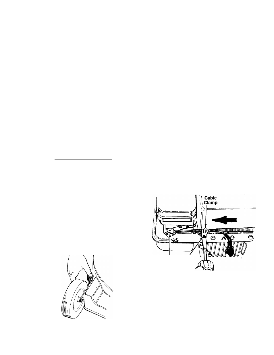
THROTTLE CONTROL ADJUSTMENT
If the throttle control needs adjustment or has been
replaced, adjust the throttle control as follows.
1.
Loosen (do not remove) the screw on the cable
clamp so that the cable will move freely under the
clamp. See figure 13.
2.
Place the throttle control lever on the handle all the
way forward to START position.
3.
Place the control lever on the engine in the full
open position by pushing it as far toward the out
side of the engine as it will go. Tighten the screw
on the cable clamp to secure the cable in this
position.
Control Screw
Lever
On Engine
FIGURE 13.
CARBURETOR ADJUSTMENTS
A
FIGURE 12.
WARNING:
If
any
adjustments
are
made to the engine while the engine
is running (e.g. carburetor), keep clear
of
all
moving
parts.
Be
careful
of
heated surfaces and muffler.
11