Bolens 115-020A User Manual
Page 3
Attention! The text in this document has been recognized automatically. To view the original document, you can use the "Original mode".
CAUTION
OPERATION
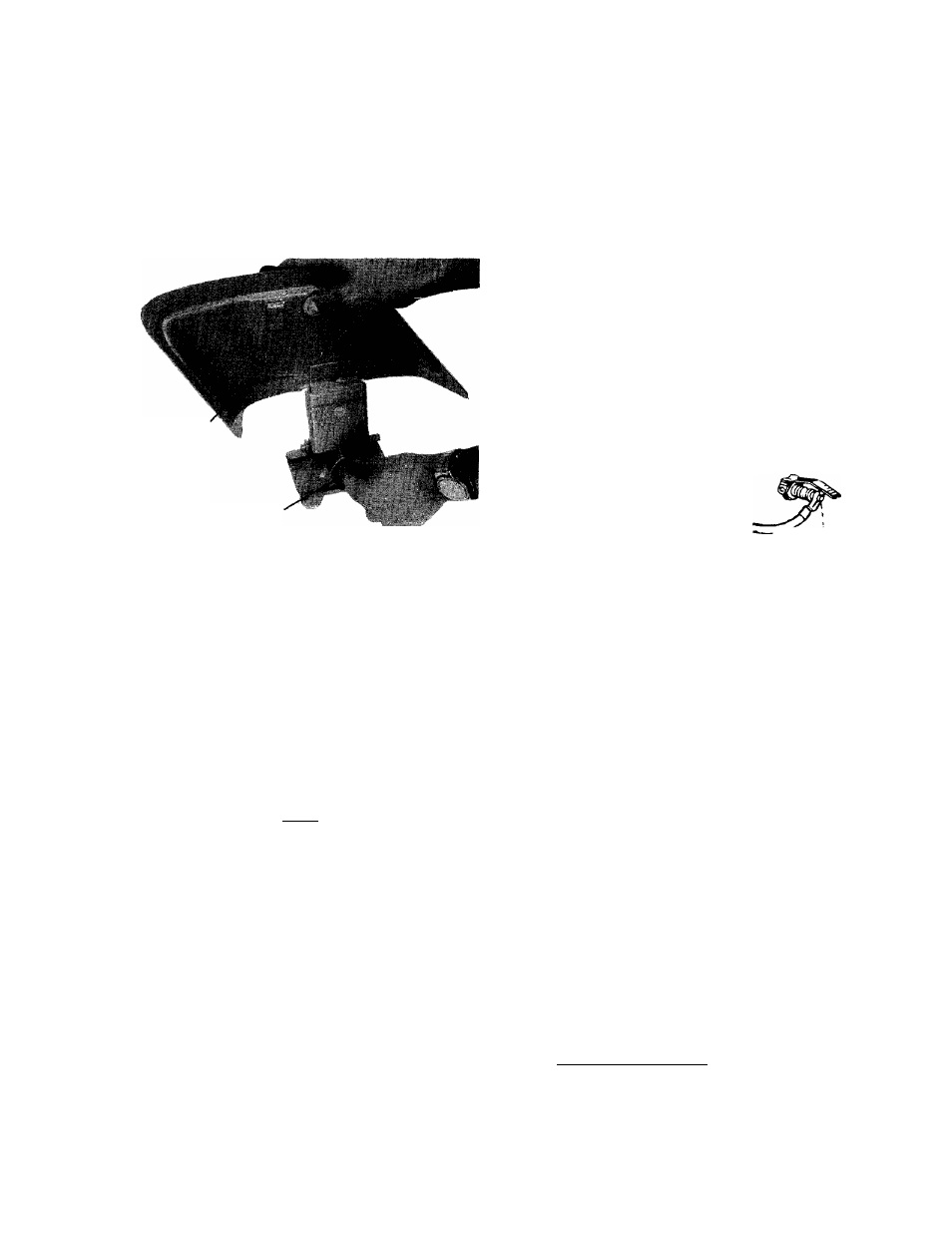
Please note that the chute deflector on
your mower is in an upright position. It
is held in that position by a shipping
block. This block is used for shipping
purposes only. It must be removed and
discarded
before
your
mower
is
put
into operation.
Chute Deflector
Shipping Block to be Removed
ASSEMBLY
Your new mower is shipped preassembled with the
exception of the handle.
1.
Remove lawn mower and all parts from the carton.
Make certain that all loose parts and literature have
been removed before the carton is discarded.
For shipping purposes, the wheels on your mower are
generally set in the upper mounting holes. Relocating
the wheels to the second holes from the bottom will
give better mowing results in most cases. When chang
ing wheel positions, be sure Belleville washers are
assembled properly. (See cutting height instructions.)
1. Service engine with gas and oil. See Engine Manual,
packed with lawn mower for complete instructions
for the care and maintenance of engine. Read Di
rections carefully.
2.
When ready to start engine, place throttle control
lever on handle in "START" position and start en
gine in accordance with instructions in engine man
ual. After engine starts, move throttle control lever
on handle to desired engine speed. The engine is
stopped by placing control lever on handle in the
"STOP" position.
Two cycle engines are constant speed engines. No
throttle control is required. The
engine
is
stopped
by
moving
the
spark
plug
shorting
lever
against
the
tip
of
the
spark
plug.
Be
sure
this
is
moved
away
before
starting
the
engine.
Shorting
w Clip Must
^Not Touch
Spark Plug
While Engine
Is Operating
3.
Be sure that lawn is clear of stones, sticks, wire, or
other objects which could damage lawn mower or
engine. For best results and to insure more even
grass distribution, do not mow when lawn is ex
cessively wet.
2.
If mower is equipped with throttle control extend
throttle control assembly which is attached to en
gine at the rear of the mower and place on the floor.
CAUTION: Do not bend or kink control wires.
NOTE
Two cycle engine are constant speed
engines—some
engines
have
manual
friction control on the engine. These en
gines require no remote throttle con
trol.
3.
Assemble the upper and lower handle parts with
cap screws and locknuts provided in parts bag. On
mower with throttle control, use the longer (yellow)
screw to attach throttle control.
4.
Floles at the bottom of the lower handle are to be
fitted over studs located in front of each rear wheel
mounting position.
5.
Secure throttle control wire to lower right handle
with cable clips.
6. Check ALL nuts and bolts for correct tightness.
ADJUSTMENTS
CAUTION
Do not at any time make any adjust
ment to lawn mower without first stop
ping
engine
and
disconnecting
spark
plug wire.
CUTTING HEIGHT
Adjustment may be made by removing and moving
wheel studs to desired position. Cutting heights will
be raised as wheel studs are moved to a lower hole
and lowered as wheel studs are moved to a higher hole
in the deck. All wheel studs must be mounted in a
relative position to the deck.
THROTTLE (OPTIONAL)
If adjustment becomes necessary, the throttle control
wire assembly can be reset as follows:
1. Loosen, but do not remove, screw securing throttle
control wire assembly at engine.