Screw – Bolens 116-312-000 User Manual
Page 6
Attention! The text in this document has been recognized automatically. To view the original document, you can use the "Original mode".
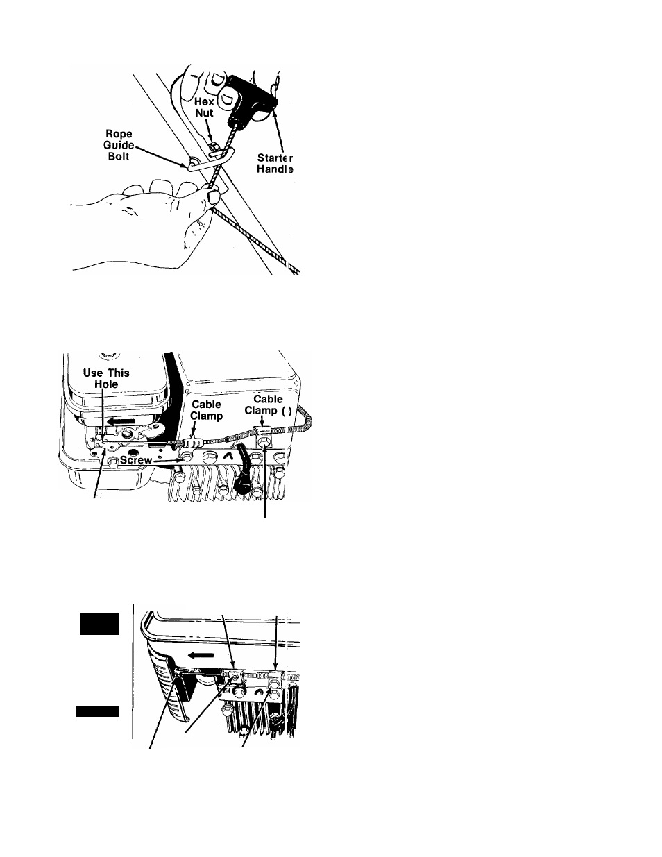
FIGURE 7.
Throttle
Control Lever
On Engine
FIGURE 8.
Remove This Screv/
Cable CabI i
Clamp
Clamp (l)i
n
m
CHOKE
q^I>SL0W
Screw
Throttle
Remove Sci ew
Control Lever
On Engine
12
13.
14.
FIGURE 8A.
9. Slip the starter rope into the rope guide bolt as
------shown in figure 7. If more slack is needed in the
starter rope, disconnect and ground the spark plug
wire. Depress the blade control handle and pull ad
ditional rope out from the engine.
10. Tighten the hex nut on the rope guide bolt
securely.
Steps 11 through 15 are for standard Briggs and
Stratton engines. If your unit is equipped with a
deluxe Briggs and Stratton engine (see figure 8A),
follow steps 11A through 15A.
Standard Engines:
11. Place the throttle control lever on the handle in
FAST position.
Route the throttle
control cable under the lower
handle and inside the handle mount bracket. Hook
the “Z” end of the throttle control cable into the
outside hole in the control lever on the engine.
Using a 7/16" wrench, remove the screw on the
engine shown in figure 8.
Remove the screw on the cable clamp shown in
figure 8. Slip the control casing under the clamp.
Replace the screw, but do not tighten (cable must
still move freely beneath the clamp).
15. Push the throttle control lever on the engine to the
full open position (as far toward the outside of the
------ unit as it will go) as shown in figure 8. Tighten the
screw to secure the throttle control cable in this
position.
Deluxe Engines:
11 A. Move throttle control lever on handle forward until
it stops in FAST position (do not push all the way
forward to CHOKE position). See figure 8A.
12A. Route the throttle control cable under the lower
handle and inside the handle mount bracket.
Hook the “Z” end of the throttle control cable in
to the hole in the control lever on the engine.
13A. Using a 7/16" wrench, remove the screw on the
engine shown in figure 8A.
14A. Remove the screw on the cable clamp shown in
figure 8A. Slip the control casing under the
clamp. Replace the screw, but do not tighten
(cable must still move freely beneath the clamp).
15A. Slide the throttle control lever on the engine as
far toward the outside of the engine as it will go
easily (just until resistance is felt) as shown in
-------- figure 8A. (Do not force it into the extreme out
side position, which is the CHOKE position.)
Tighten the screw to secure the throttle control
cable in this position.
All Units:
16.
Loosen the screw on the clamp on the side of the
engine. Secure the cable away from the muf
fler. Be careful not to bend or kink the cable.
Tighten the screw.
17.
Secure cable casing to the front of engine with
cable clamp (I) provided in hardware pack and
screw removed from engine in step 13 (or 13A).
Do not overtighten.