Bolens 24596-9 User Manual
Page 6
Attention! The text in this document has been recognized automatically. To view the original document, you can use the "Original mode".
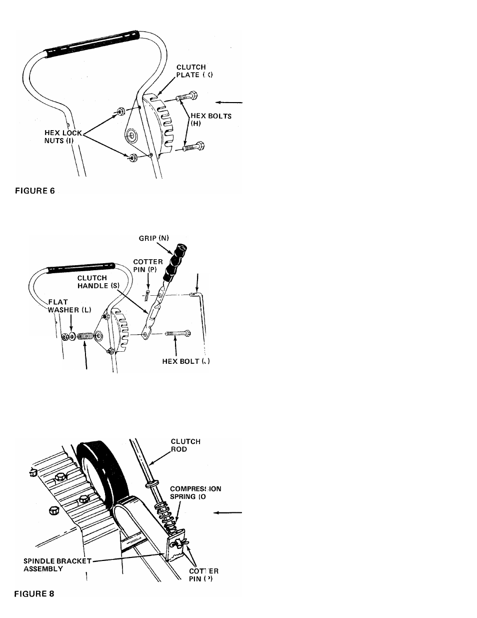
7. Place clutch plate (X) on the left hand side of the
upper handle as shown in figure 6. Secure in
place with hex bolts (H) and hex lock nuts (I).
CLU
CH
ROD (U)
HEX
LOCK-T
NUT (M)
1
COMPRESSION
SPRING (K)
8.
Place hex bolt (J) through bottom hole in clutch
handle as shown in figure 7, then through hole in
adjustment bracket.
9.
Secure hex bolt with compression spring (K),
flat washer (L) and hex lock nut (M) on the inside
of the adjiistment bracket.
FIGURE 7
10.
Place compression spring (0) over straight end
of clutch rod (U). Place‘end of rod in spindle
bracket assembly and secure with cotter pin (P).
See figure 8.
11. Secure bent end of clutch rod to clutch handle
with cotter pin (P). See figure 7.
12. Slip the handle grip (N) on the end of the clutch
handle. It will slip on more easily if it is first
soaked in warm, soapy water.