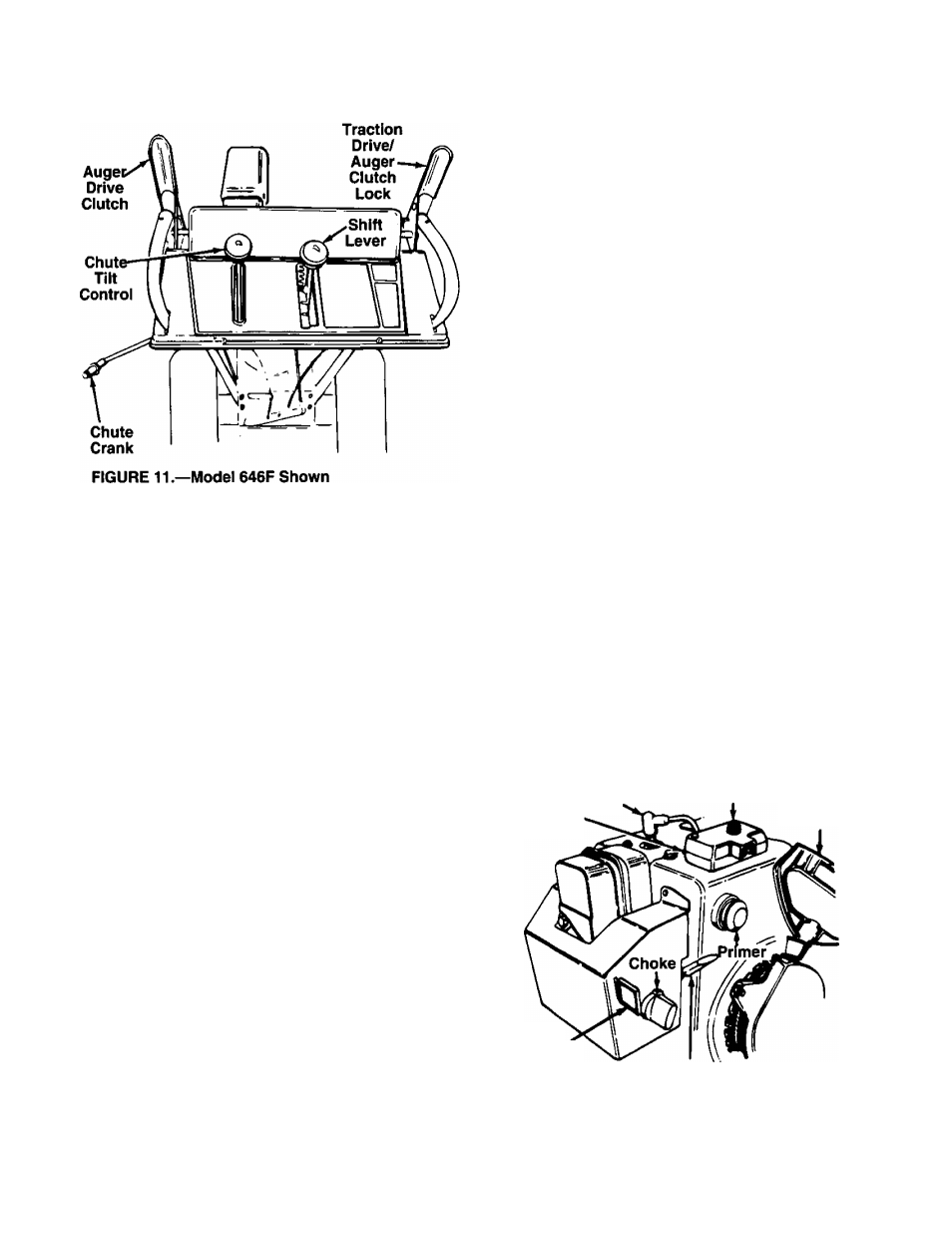
Shift lever, Traction drive/auger clutch lock, Chute tilt control (see figure 11) – MTD White 315E646F190 User Manual
Page 8: Throttle control (see figure 13), Safety ignition switch (see figure 13), Controls
Attention! The text in this document has been recognized automatically. To view the original document, you can use the "Original mode".
CONTROLS
FIGURE 12.
SHIFT LEVER
(See figures 11 and 12)
The shift lever is located in the center
of the handle panel. The shift lever may
be moved into one of eight positions.
Run engine with throttle in the fast posi
tion. Use the shift lever to determine
ground speed.
Forward—one of six speeds. Position
number one (1) is the slowest. Position
number six (6) is the fastest.
Reverse—two reverse (R) speeds. “R”
closest to the operator (all the way
back) is the faster of the two.
AUGER DRIVE
(See figure 11)
The auger drive clutch is located on the left handle.
Squeeze the clutch grip to engage the augers.
Release to stop the snow throwing action. (Traction
drive clutch must also be released.)
TRACTION DRIVE/AUGER CLUTCH LOCK
(See figure 11)
The traction drive clutch is located on the right handle.
Squeeze the traction drive clutch to engage the wheel
drive. Release to stop.
This same lever also locks the auger clutch so you
can turn the chute crank without interrupting the snow
throwing process. If the auger drive clutch is engaged
with the traction drive clutch engaged, the operator
can release the auger drive clutch (on the left handle)
and the augers will remain engaged. Release the
traction drive clutch to stop both the augers and wheel
drive (auger drive clutch must also be released).
CHUTE CRANK
(See figure 11)
The chute crank is located on left hand side of the
snow thrower.
To change the direction in which snow is thrown, turn
chute crank as follows:
1. Crank clockwise to discharge to the left.
2. Crank counterclockwise to discharge to the right.
CHUTE TILT CONTROL
(See figure 11)
Models 646F and 666H only: The distance snow is
thrown can be adjusted by adjusting the angle of the
chute assembly. Move the chute tilt control fonvard to
decrease the distance, toward the rear to increase.
Model 616E only: To adjust chute assembly, loosen
the hand knob. Pivot the top of the chute assembly to
position desired. Retighten the hand knob. The sharp
er the angle, the shorter the distance snow is thrown.
THROTTLE CONTROL
(See figure 13)
The throttle control is located on the engine. It regu
lates the speed of the engine.
SAFETY IGNITION SWITCH
(See figure 13)
The ignition key must be inserted in the switch before
the unit will start. Remove the ignition key when snow
thrower is not in use.
Switch
Box
Spark
Plug
Starter
Button
Rope Starter
Handle
Ignition
Key
Throttle
Control
FIGURE 13.—Model 646F Shown