Assembly, Instructions, Figure 1 – MTD 110-328A User Manual
Page 4: Note, Assembly instructions
Attention! The text in this document has been recognized automatically. To view the original document, you can use the "Original mode".
ASSEMBLY
INSTRUCTIONS
Assembly
of
Mower
A
G-
H ■
I-
Assembly
of
Grass
Catcher
FIGURE 1.
II
Contents of Hardware Pack
A (2) Hand Knobs
B (2) Curved Carriage Bolts 5/16-18 X 1.75" Long
— C (2) Cable Ties
D (1) Hex Screw V4-20 x 1.50" Long
E (1) Hex Center Lock Nut V4-20 Thd.
F (2) Hairpin Cotters
G (7) Truss Head Bolts 3/8" Long
H (7) External Lock Washers
I (7) Hex Nuts #10-24 Thread
■J (2) Cotter Pins
K (2) Tubing Connectors
1. Remove the lawn mower, loose parts, hard
ware pack and literature from the carton.
Make certain all parts and literature have been
removed before the carton is discarded.
2. Extend the throttle control which is attached
to the mower and piace on the floor. Be
careful not to bend or kink control wire.
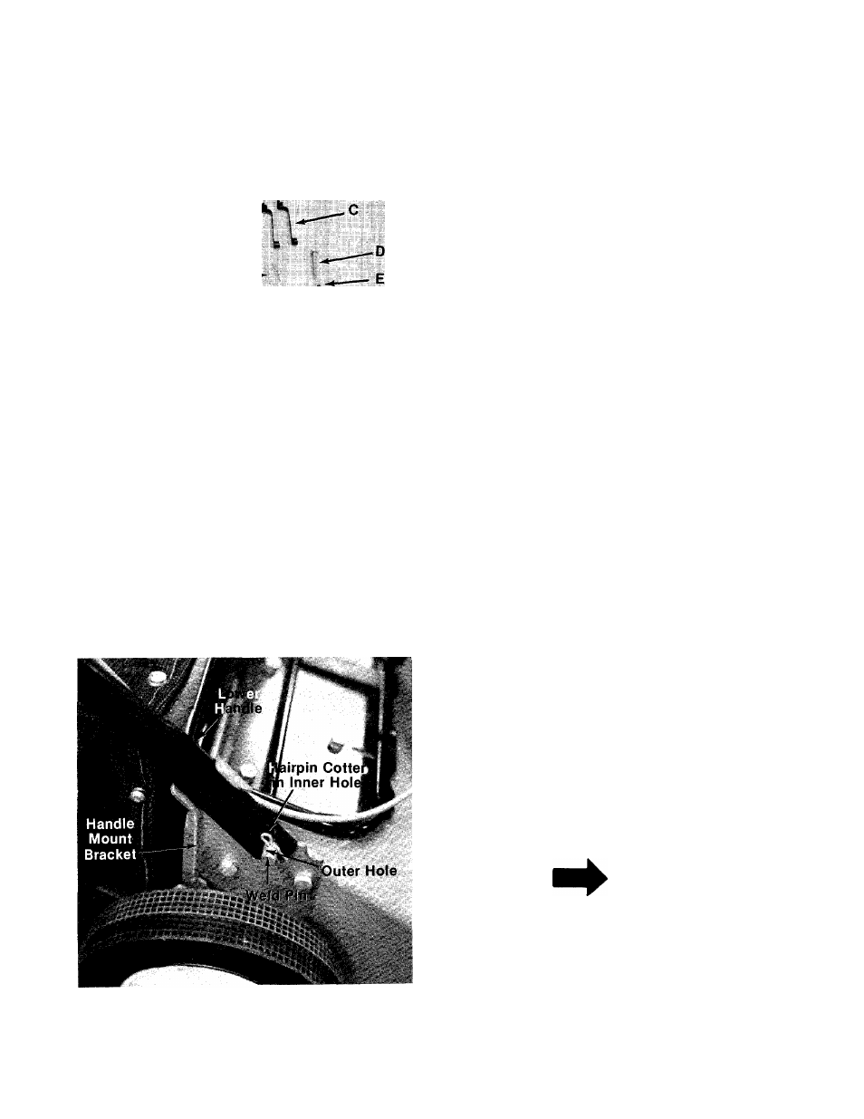
3. Piace lower handle in position over weid pins
in handle mount brackets on deck. Secure by
placing two hairpin cotters (F) in inner hoie on
— weld pins. See figure 2.
NOTE
It may be necessary to bend the
ends of the lower handle inward
slightly to assure a snug fit against
the bracket mounting area.
FIGURE 2.