Transaxle motion control le¥er i, Remove wheel for repairs (see fig. 2s), Iont wheel toe-in/camber – Poulan 168737 User Manual
Page 23
Attention! The text in this document has been recognized automatically. To view the original document, you can use the "Original mode".
- I f l ì .
-
TRANSAXLE
MOTION
CONTROL
LE¥ER
i
JSTMENT (See
Fig.
25)
The motion control lever has been preset at the factory and
adjustment should not be necessary.
•
Loosen adjustment bolt in front of the right rear
wheel,
and lightly tighten.
® Start engine and move motion control lever until tractor
does not move forward or backward.
*
Hoid motion control lever in that position and turn
engine off.
•» While holding motion
control lever
in
place,
loosen the
adjustment bolt.
Move motion control lever to the neutral (N) (lock gate)
position.
NOTE; If
ment bolt,
id to get to adj usi
le lowest position.
liter above adjustment is made,
U . C i _ _ C i * - i V .
t r - ' l i r
osition, follow these steps:
Loosen the adjustment boil.
Mr ve . - r,i . '' ,
, - j ,
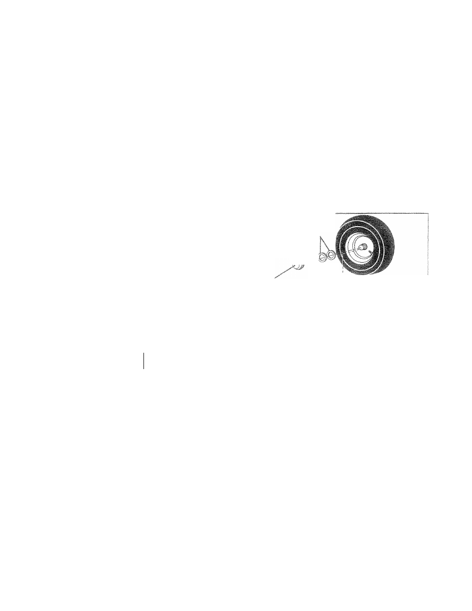
(j! ' I.,it- I f .r i~ '( ' V O h i l i ’ ' a c t O ’ ' ‘ “ f e c t , C ' 3 b . ..imr , seo« TO REMOVE WHEEL FOR REPAIRS (See Fig. 2S) » Block up axle securely. * Remove axle cover, retaining ring and washers to allow wheel removal (rear wheel contains a square key - Do not lose). « Repair tire and reassemble, ® On rear wheels only: align grooves in rear wheel hub and axie. Insert square key. s Repiace washers and snap retaining ring securely in axle groove. * Replace axle cover. NOTE: To seal tire punctures and prevent flat tires due to WASHERS RETAINING aiNG 1/2 inc /5 Ul !ilf bet AXLE COVER SQUARE KEY (REAR WHEEL ONLY) I „ f o r :VEF 1» dA i r TO HTTP 5^*^ "j - IF 'm & ^ „ J U' „ ' Æ ■■■■ ..V ./ 5 ¿Cu r:vc.-*T T. — T : Ljhouid your [isnsmission r©c|U{r8 rGmovsf for sorvic© or Sc 't -n I r h„ • j«: -'m re i"'wt!Piini> ^r-r opem if j I See ‘'- j RD c :TRA'' j SMIL- L C N ' - n i h £ o n -«„tor.., n,= ncfuai. TO ADJUST STEERING WHEEL ALIGNMENT if steering wheel crossbars are not horizontal (left to right) when wheels are positioned straightforward, remove steer iONT WHEEL TOE-IN/CAMBER ie front wheel toe-in and camber are not adjustable on ,our tractor, if damage has occurred to affect the front .aeei toe-in or camber, contact your nearest authorized ervics center/departmeni. 23 If i ■ I - . recharged. (See “BATTERY" inthe CUSTOMER RESPON- '-'iE* _i~ - -jt - - f ‘ ' l~C" r" - , T.is ¡.mc“-’jre MFCR^AYT F 'O l " n EG m I • c q P C ' ! 'DC ~ z ' ^ - r „ L i VE-' i C l .E A,_3G B£ ¡ED‘~~ CROUNDEC SrO”5Y l ... v: , 1 3 - ^ V . F T R q C O F EATTEF ' T3 3 . AR~" C S~T^_E£. TO ATTACH JUMPER CABLES - » Connect each end of the RED cable to the POSITIVE (+) terminal of each battery, taking care not to short against chassis. ® Connect one end of the BLACK cable to the NEGA TIVE (-) terminal of fully charged battery. • Connect the other end of the BLACK cable to good CHASSIS GROUND, away from fuel tank and battery. TO REMOVE CABLES, REVERSE ORDER - ® BLACK cable first from chassis and then from the fully charged battery. • RED cable last from both batteries.
.slow leaks, tire sealant may be purchased from your local
parts dealer. Tire sealant also prevents tire dry roi and
corrosion.
BOLT
ing wheel and reassemble per instructions in the Assembly
section of this manual.