P1 c – CH Tech Quad M-module Carrier i4000 User Manual
Page 18
i4000 - Quad M-module carrier for VMEbus
User Manual
Version: 1.2
AcQuisition Technology bv
P.O. Box 627, 5340 AP
Page 18 of 25
Oss, The Netherlands
4.4.
VME
BUS
P1 C
ONNECTOR
A
SSIGNMENTS
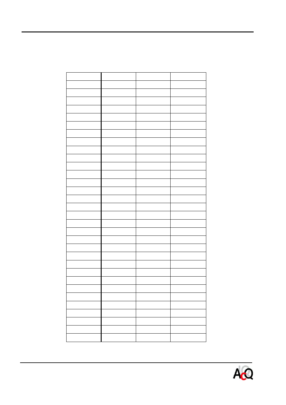
The following table provides signal names for the VMEbus P1 connector as used by the i4000. The connector
consists of three rows of pins labelled rows A, B and C.
Pin
Row A
Row B
Row C
01
D00
D08
02
D01
D09
03
D02
D10
04
D03
BG0IN*
D11
05
D04
BG0OUT*
D12
06
D05
BG1IN*
D13
07
D06
BG1OUT*
D14
08
D07
BG2IN*
D15
09
GND
BG2OUT*
GND
10
SYSCLK
BG3IN*
11
GND
BG3OUT*
12
DS1*
RESET*
13
DS0*
LWORD*
14
WRITE*
AM5
15
GND
A23
16
DTACK*
A22
17
GND
A21
18
AS*
A20
19
GND
A19
20
IACK*
GND
A18
21
IACKIN*
A17
22
IACKOUT*
A16
23
AM4
GND
A15
24
A07
IRQ7*
A14
25
A06
IRQ6*
A13
26
A05
IRQ5*
A12
27
A04
IRQ4*
A11
28
A03
IRQ3*
A10
29
A02
IRQ2*
A09
30
A01
IRQ1*
A08
31
-12V
+12V
32
+5V
+5V
+5V