To stop engine, Operating the chipper, Adjustments – MTD Yard-Man 203b User Manual
Page 6: Front caster wheels, Nozzle door height adjustment
Attention! The text in this document has been recognized automatically. To view the original document, you can use the "Original mode".
TO STOP ENGINE
1. To stop engine, move throttle control lever to OFF
position.
2. Disconnect spark plug wire and ground to prevent
accidental starting whiie equipment is unattended.
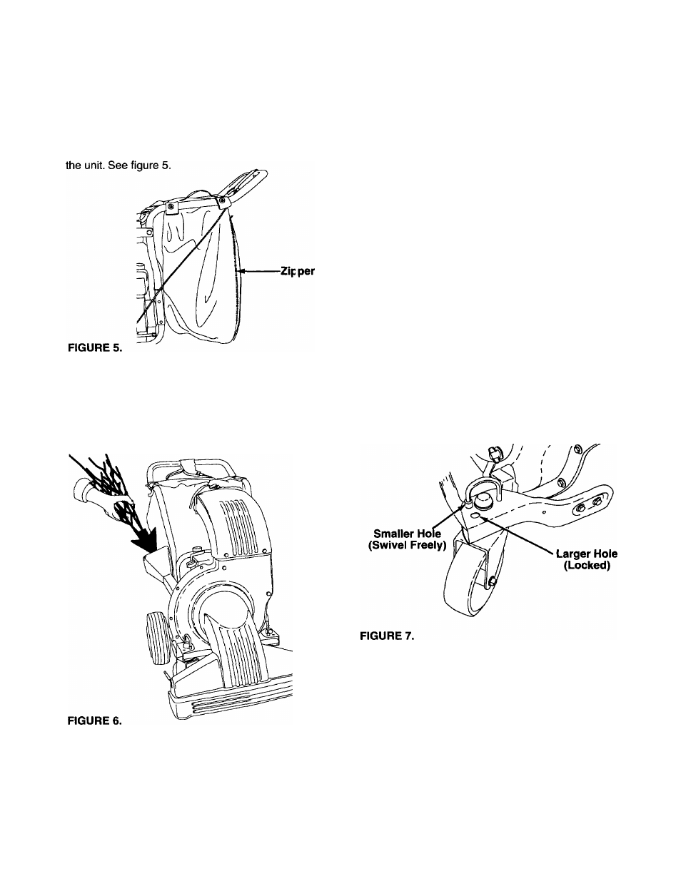
IMPORTANT: Open the large zipper to emcty the
bag. Be certain the zipper is ciosed when operating
OPERATING THE CHIPPER
Do not attempt to shred or chip any material other than
vegetation found in a normal yard (i.e., branches,
leaves, twigs, etc.). Materiai such as staiks cr heavy
branches up to 2" in diameter may be fed into tie chip
per chute. See figure 6.
A
WARNING: Material up to a maximum of
2" in diameter may be fed into the chipper
chute. Do not attempt to shred or chip any
material larger than 2" in diameter. Per-
sonai injury or damage to the machine
could result.
IMPORTANT: There is a flail screen located inside the
housing in the discharge area. If the flail screen
becomes clogged, remove and clean as instructed in
the Maintenance section on page 8. For best
performance, it is important to keep the chipper biades
sharp. Refer to Maintenance section, page 8. If the
composition of the material being discharged changes
(becomes stringy, etc.) or if the rate at which the
material is discharged slows down considerably, it is
iikeiy that the chipper blades are dull and need to be
sharpened or replaced.
ADJUSTMENTS
A
WARNING: Do not at any time make any
adjustment to the unit without first stop
ping engine and disconnecting spark plug
wire.
FRONT CASTER WHEELS
Your chipper-shredder-vacuum is equipped with caster
front wheels. The casters can be locked in a straight
ahead position or can be left to swivel freely. Lift and
place pins in the larger holes for locked, straight ahead
operation. Place pins in smaller holes to allow casters
to rotate freely. See figure 7. Lock wheels in straight
position when operating on slopes.
NOZZLE DOOR HEIGHT ADJUSTMENT
The nozzle door can be adjusted to any of five posi
tions, ranging from 1/2" to 3" ground clearance. See
figure 8. The nozzle door height has to be adjusted
according to the conditions.
Slide the height adjustment lever forward or backward
for adjusting the nozzle door upwards or downwards.
NOTE: In general, raise the nozzle height to vacuum a
thick layer of leaves; lower the nozzle height for
smoother surfaces.