MTD Yard-Man 203b User Manual
Page 10
Attention! The text in this document has been recognized automatically. To view the original document, you can use the "Original mode".
11. Remove the two hex bolts and hex lock nu s which
extend through the housing. Lift the flail screen
out of the housing. See figure 11.
12. Remove the outer housing and housing blades by
removing the fourteen seif-tapping screws
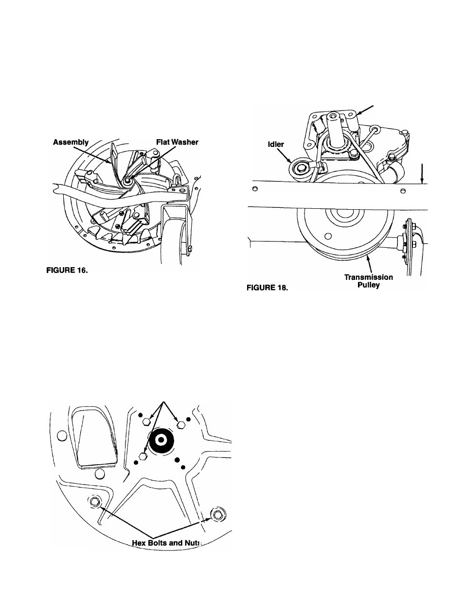
13. Remove the hex bolt, lock washer and flat washer
that secures the impeller assembly to tho crank
shaft. See figure 16.
Impeller
Hex Bolt,
Lock Washer and
14. Thread the special impeller tool (see
previous page) into the crankshaft. Stop v
impeller assembly can move on the crank
If the old belt is still on the unit, cut I
remove.
15.
lote on
'hen the
shaft.
seit and
16. Remove the impeller assembly from this crank
shaft. Unthread the special impeller tool rom the
impeller assembly.
17. Remove the inner housing and mounting adapter
by removing the five hex bolts and two f ex nuts.
See figure 17.
Hex Bolts
18. Insert the new belt between the frame and trans
mission pulley. It may be necessary to use a
screwdriver to pry the frame away from the pulley
in order to insert the belt. Apply a slight upward
pressure, being careful not to damage the pulley.
Place belt around transmission pulley. See figure
18.
Mounting
Adapter
Frame
FIGURE 17
19. Press down on the belt guard spring by the idler
pulley and release spring from the slot on the idler
bracket. Place the belt on the idler pulley and
place belt guard spring back into the slot on the
idler bracket. See figure 18.
20. Place the mounting adaptor against the engine.
Make sure the hole for the belt guard screw is
facing up. See figure 18.
21. Place the inner housing against mounting adapter
and frame. Secure with the five hex bolts and two
hex nuts removed in step 17.
22. Slide the impeller assembly onto the crankshaft.
Place a screwdriver under the belt, and turn the
impeller assembly counterclockwise to seat the
belt into the slot on the impeller. Make sure the
belt is routed inside all belt guards.
23. Secure the impeller assembly to the crankshaft
using the hex bolt, lock washer and flat washer
that was removed in step . Torque the bolt to 550
in. lbs. min., 700 in. lbs. max.
24. Place the housing blades against the inner hous
ing. The blades must be place as shown in figure
19.
10