Removing unit from carton, Tools required, Disgonneeting spark plug – Troy-Bilt 466 User Manual
Page 7: Assembling handle
Attention! The text in this document has been recognized automatically. To view the original document, you can use the "Original mode".
SECTION 3: ASSEMBLING YOUR LAWN MOWER
Removing Unit From Carton
•
Remove staples, break glue on top flaps or cut tape
at carton end and peel along top flap to open
carton.
•
Remove loose parts If Included with unit (I.e.,
operator's manual, hardware pack etc.).
•
Cut corners and lay carton down flat. Remove
packing material.
•
Roll or slide unit out of carton. Check carton
thoroughly for loose parts.
NOTE:
Make sum not to crimp cables while removing
loose parts or the entire unit from the carton.
Tools Required
•
Pair of Pliers
•
Funnel
•
Set of adjustable wrenches
DisGonneeting Spark Plug
•
Before setting up your lawn mower, disconnect the
spark piug wire from the spark piug, and attach
rubber boot to a boit on the engine to ground. See
Figure 1 .
Figure 1
NOTE:
Reference to right or left hand side of the mo wer
is observed from the operating position.
IMPORTANT:
This unit Is shipped without gasoline or oil
In
the engine. Be certain to service engine with gasoline
and oil before operating your mower.
Assembling Handle
• For shipping purposes, the grass bag was placed
on top of the unit. Remove it from the unit and set it
out of the way. See Figure 2 .
Lower Hantle
Upper Handle
Lift upper
handle^
Lift lower handle
Grass
Figure 2
Raise the lower handle, as shown In Figure 2 , till it
snaps into place.
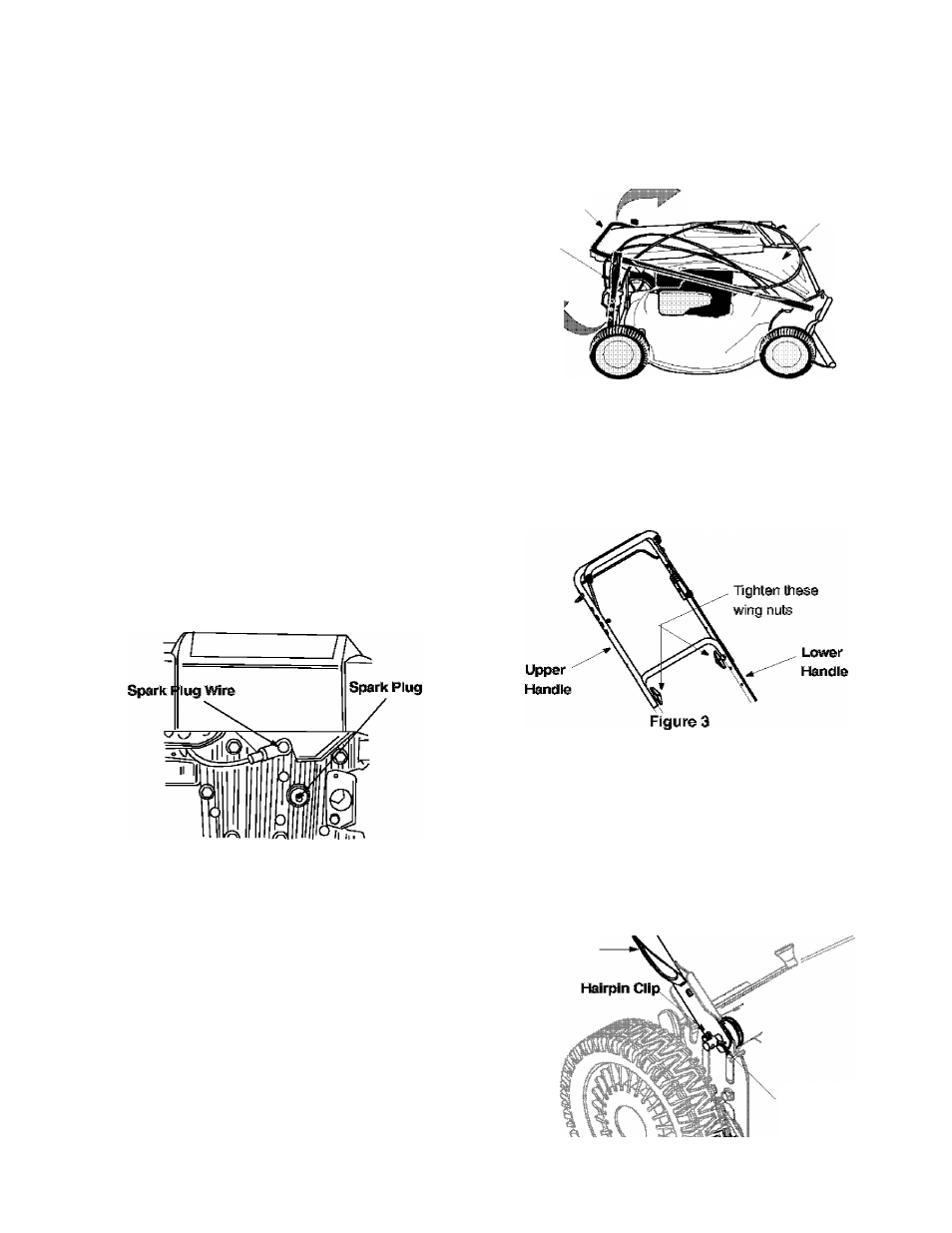
Raise the upper handle as shown In Figure 2 .
Tighten the two wing nuts which are already on the
handle. See Figure 3 .
NOTE:
Make sure to route the cables outside the lower
handle. Also do not crimp the cables while lifting die
handle up.
•
For shipping purposes, the hairpin clip is placed in
the outer hole of the weld pin on the lower handle.
Remove the hairpin clip from the outer hole of the
weld pin.
•
Using a pair of pliers, insert the hairpin clip into the
inner hole in the weld pin. Repeat on the other side.
See Figure 4.
Lower Handle -
Inner Hole
Figure 4