Assembly instructions, Nozzle :—-—air, Unpacking – MTD 242-685-000 User Manual
Page 3: Loose parts in carton, Tow bar kit, Ahaching the nozzle (hardware a), Attaching the upper handle (hardware b)
Attention! The text in this document has been recognized automatically. To view the original document, you can use the "Original mode".
ASSEMBLY INSTRUCTIONS
IMPORTANT: This unit is shipped WITHOUT
GASOLINE or OIL. After assembly, service engine
with gasoline and oil as instructed in the separate
engine manuai packed with your unit.
Upper
Nozzle
:
—
-
—
A
i
r
Duct
-Assembly
Directional
Discharge
Assembly
Impeller
Guard
Clutch
Rod
(Self-Propelled
Models Only)
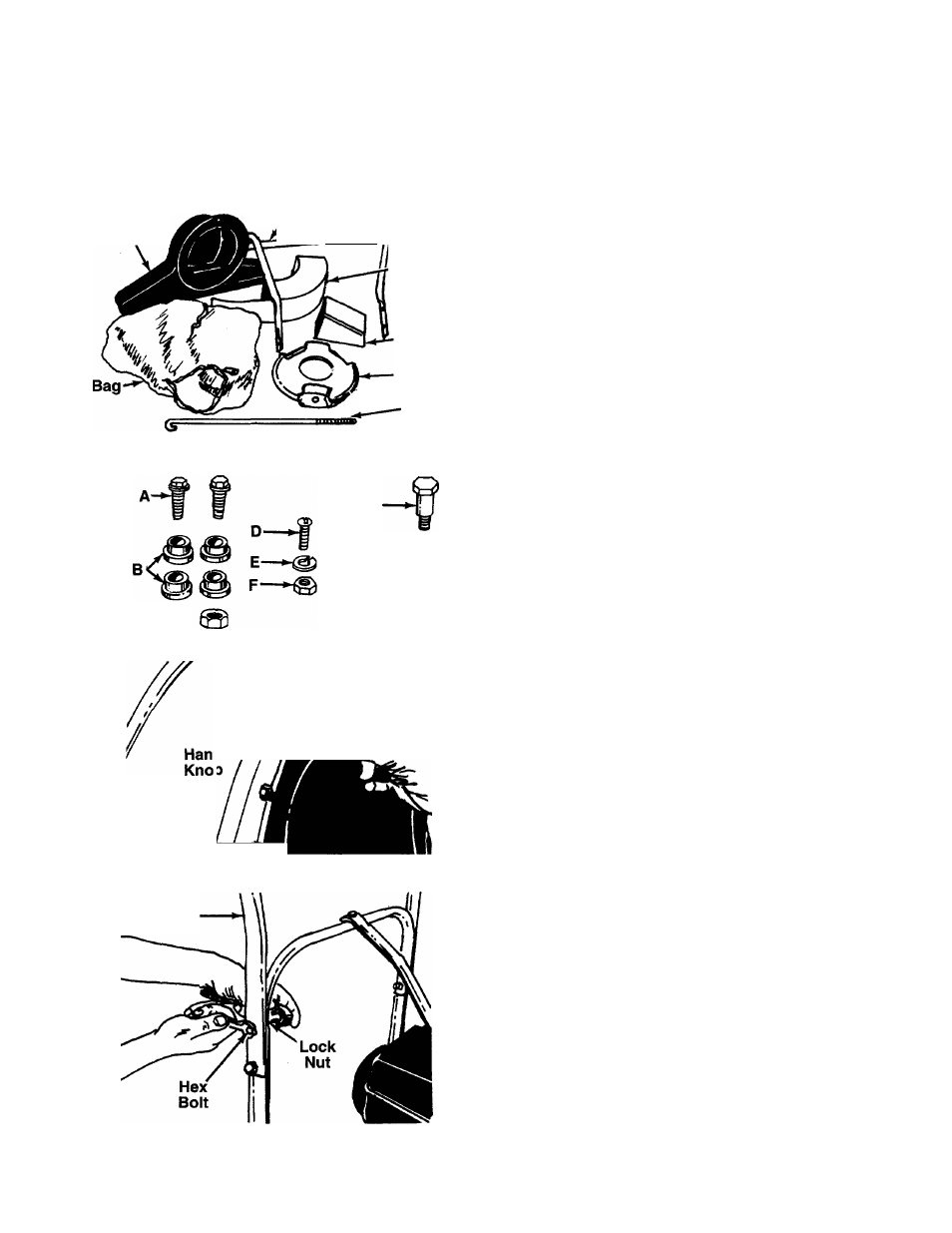
FIGURE 2.-Loose Parts in Carton
C~*@
FIGURE 3.
Nozzle
NOTE: Reference to right or left hand side of the
vacuum is observed from behind the unit in the
operating position.
UNPACKING
Remove the vacuum, loose parts, hardware pack and
literature from the carton. Make certain all parts and
literature have been removed before the carton is dis
carded.
LOOSE PARTS IN CARTON
-(See Figure 2)
(1) Nozzle
(1) Upper Handle
(1) Air Duct Assembly
(1) Clutch Rod (Self-Propelled Models Only)
(1) Directional Discharge Assembly
(1) Impeller Guard
(1) Bag
TOW BAR KIT
Standard for push models, optional for self-pro
pelled models.
-(See Figure 3)
A (2) Hex Bolts 5/16-18 x 1” Long
B (4) Shoulder Spacers
C (2) Hex Nut 5/16-18 Thread
D (1) Truss Machine Screw 1/4-20 x 3/4” Long
E (1) Lock Washer 1/4” I.D.
F (1) Hex Nut 1/4-20 Thread
G (1) Shoulder Bolt
H (2) Cupped Washers 3/8” I.D.
I (1) Hex Jam Lock Nut 3/8-16 Thread
(2) Tow Bar Halves (Not Shown)
AHACHING THE NOZZLE (Hardware A)
Place nozzle in position on front of housing so that it
rests in flanges. Secure with one hand knob and
cupped washer (cupped side of washer against the
-nozzle). See figure 4.
/ /
7
FIGURE 4.
Upper
Handle
ATTACHING THE UPPER HANDLE (Hardware B)
Place the upper handle in position over lower handle.
Fasten with four hex bolts and lock nuts provided.
-See figure 5. Two 7/16” wrenches are required.
FIGURE 5.