Ignition, Ignition 13 – Generac Power Systems TXP User Manual
Page 81
Attention! The text in this document has been recognized automatically. To view the original document, you can use the "Original mode".
IGNITION
13
The engine Ignition System is a solid state capacitor discharge type,
often called a "breakerless” system due to the absence of breaker
points. The system consists of the following components:
1, Engine flywheel magnet
2, Ignition stator
3, Ignition Module
4, Ignition Coil
5, Spark Plugs
5. Interconnecting wiring
G E N E R A L
O P E R A T I O N
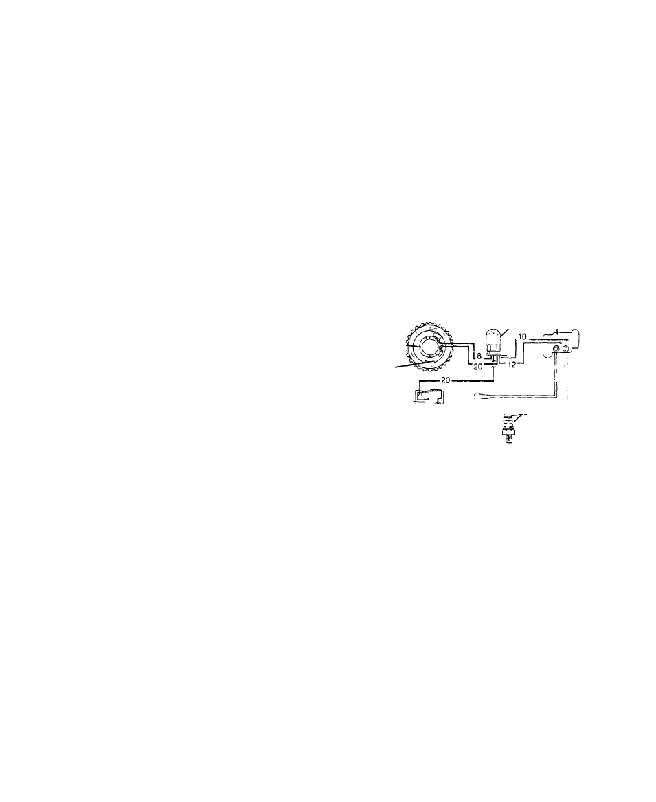
Engine rotati.on causes the starter
ring gear to turn. A magnet rotates
with the ring gear to induce curr
ent flow into the charge and trigg
er coils of the Ignition Stator.
Current flow from the Charge coil
passes through Wire #8 and charges
a capacitor in the Ignition Module,
At 26° BTDC of the engine piston
stroke, current flow from the Igni
tion Stator trigger coil is deliver
ed through Wire rr20 to the base of a
transistor in the Ignition Module,
causing the Ignition Module capacitor
to discharge. The capacitor discharg
es through Wire #12, through the Ig
nition coil primary windings, and
through Wire #10 to ground. Current
flow through the coil primary wind
ings induces a high voltage into the
ignition coil secondary windings to
fire the spark plug gaps.
Starter Ring Gear
I
Ignition
Module
Ignition
Coil
Ignition Stator
Magnet
Low Oil
Level Shutdown
Switch -im
Spark Plugs
I
S P A R K P L U G S
Use a Champion J-8, Auto-Lite A-71, or AC, No, GC-46 spark plug. Set
plug gap to 0,030 inch. Clean spark plugs with pen knife or with wire
brush and solvent, LO NOT GRIT BLAST, Replace plug if electrodes are
burned away or if porcelain is cracked.
Issued 4-78
13.1