Generac Power Systems TXP User Manual
Page 59
Attention! The text in this document has been recognized automatically. To view the original document, you can use the "Original mode".
ENGINE
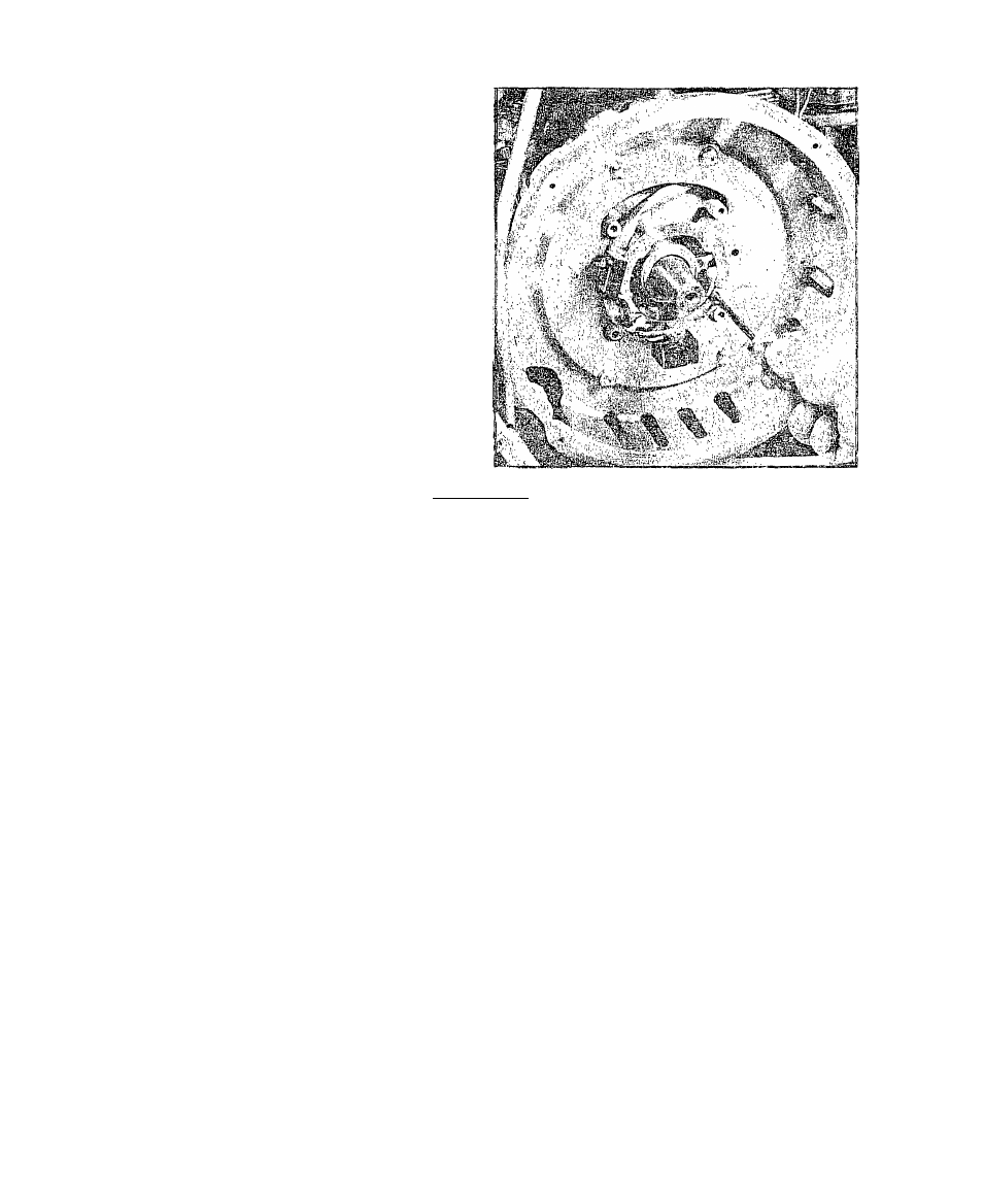
ADAPTER
IGNITION STATOR
1, The Engine Adapter Housing is
retained to the engine by four 5/8-
16 X 1 inch long button head screws.
To remove Engine Adapter Housing,
remove these screws,
2, Use a 5/16 inch nut driver to re
move four screws that retain the Ig
nition Stator to the Engine Adapter
Housing, Remove the Ignition Stator,
INSPECTION
1, Check Engine Adapter Housing for cracks, or other damage. Replace,
if damaged,
2, Inspect Ignition Stator locating, dowel pin for damage,
3, Set VOM to ''+DC and to "Rxl" scale. Zero the meter. Connect one
meter probe to the Wire #20 connection at the wiring disconnect, and
the other test probe to the metal ring of the Ignition Stator, Meter
needle should swing upscale and read approximately 6 Ohms. If needle
does NOT swing upscale. Ignition Stator Trigger Coil is ’’open”.
4r Set VOM to ”+DC” and to ’’RxlOO” scale. Zero the meter. Connect one
test probe to the Wire #8 connection at the wiring disconnect and the
other probe to the Stator metal ring. Meter needle should swing upscale
to approximately 225 Ohms. If needle does not swing upscale, the Sta
tor Charge Coil is ’’open”.
6.6
Issued 3-78