Ahaching the chute deflector (see figure 2), Ahaching the upper guide assembly (hardware a), Ahaching the hopper assembly (hardware b) – MTD 243-645C000 User Manual
Page 4
Attention! The text in this document has been recognized automatically. To view the original document, you can use the "Original mode".
A
WARNING: Make certain the spaijk plug
wire is disconnected and moved away
from the spark plug before asseinbling
the shredder.
Housing
Hopi^r Assei nbly
Hopper Pivot
Assemble ™r\^/
Truss Screw and \'/i
Nut First
Release
Bar
Upper
Guide
Extension
Remove T russ
' Upper Screw and Nut
Guide
Assembly
FIGURE 4.
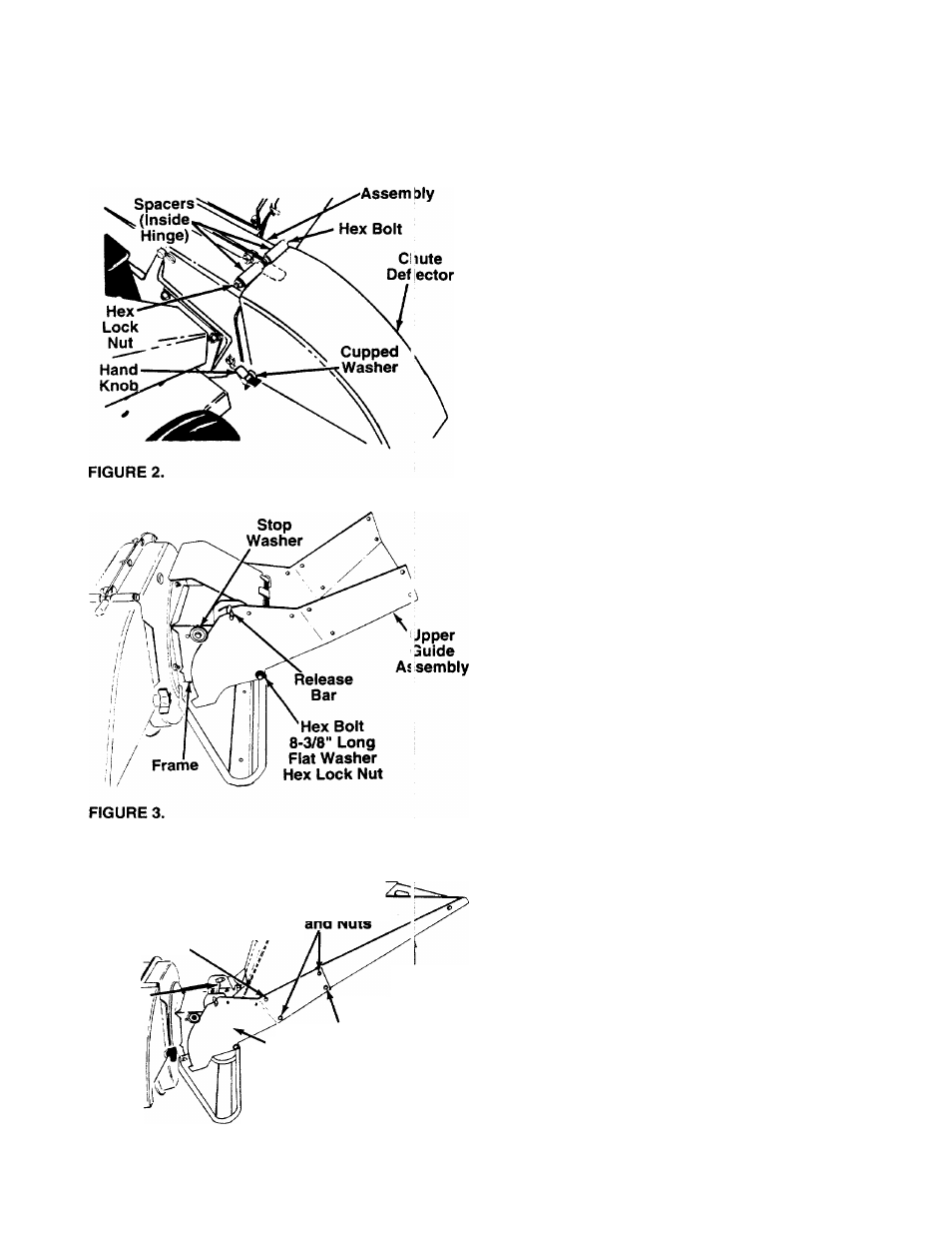
AHACHING THE CHUTE DEFLECTOR
(See Figure 2)
1. Remove the hand knobs and cupped washers
from each side of the discharge opening on the
left side of the shredder.
2. Remove the hex lock nut, two spacers and hex
bolt from inside the hinge on the housing assem
bly. Do not remove one spacer from the hex bolt.
—3. Place the chute deflector in position on the dis
charge opening on the left side of the shredder.
Insert hex bolt and spacer through hinge on chute
deflector and housing (spacer fits inside of hinge).
4. Place the second spacer over the hex bolt, inside
the other part of the hinge. Secure with hex lock
nut. Tighten securely.
5. Secure both sides of the chute deflector to the
housing using the hand knobs and cupped wash
ers (cupped side of washers go against the chute
deflector).
A
WARNING: Do not operate this shredder
unless the chute deflector has been
properly installed and is secured with the
hand knobs.
AHACHING THE UPPER GUIDE ASSEMBLY
(Hardware A)
Place upper guide assembly in position on frame,
making certain edges of the upper guide assembly
are underneath stop washers, and the release bar is
-in the slots. See figure 3. Insert hex bolt 8-3/8" long
through upper guide assembly and frame. Secure
with flat washer 5/16" I.D. and hex lock nut.
NOTE: Make certain upper guide assembly can pivot
by puiling up on release bar and lowering upper guide
assembly. If necessary, loosen hex lock nut a turn or
two. Put the upper guide assembiy back into the
raised position.
AHACHING THE HOPPER ASSEMBLY (Hardware B)
Your shredder has been shipped with the upper guide
extension attached to the hopper assembly. See fig-
-ure 4. Attach the hopper assembly to the upper guide
assembly as follows. Be certain to place heads of all
truss machine screws inside of hopper assembly.
1
. Remove one truss machine screw and nut from
each side of hopper assembly as shown in figure
4. Push hopper pivot door down inside lower
part of hopper as you place hopper assembly
(both pieces) inside upper guide assembly.
Replace truss screws and nuts just removed,
using the front upper hole in assembly as shown
in figure 4, one on each side. Tighten finger tight
only.
2. Place the six truss machine screws and nuts
found in hardware pack in the remaining holes of
hopper assembly, alternating sides of the unit and
tightening finger tight only.
3
. After assembling all eight screws, tighten them
securely.