Assembly instructions – MTD 249-660-000 User Manual
Page 4
Attention! The text in this document has been recognized automatically. To view the original document, you can use the "Original mode".
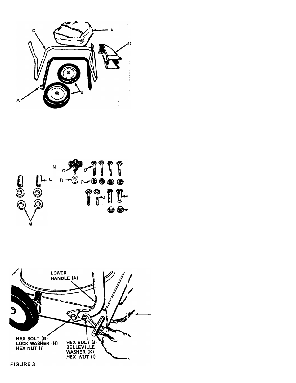
FIGURE 1
%
®-
ASSEMBLY INSTRUCTIONS
TOOLS REQUIRED:
(2) 9/16" Wrenches
(2) 7/16" Wrenches
(1) Hammer or Rubber Mallet
LOOSE PARTS IN CARTON (See figure 1):
A
(1)
Lower Handle
B
(2)
Rear Wheels
C
(1)
Upper Handle
D
(1)
Air Duct Assembly
E
(1)
Bag
CONTENTS OF HARDWARE PACK (See figure 2):
G
H
(
2
)
(
2
)
I
(4)
J
(2)
■K
(2)
L
(2)
M
(4)
N
(2)
0
(4)
P
(4)
Q
(1)
R
(1)
S
(2)
T (2)
Hex Bolts 3/8-16
X
3/4" Long
Lock Washers 3/8" I.D.
Hex Nuts 3/8-16 Thread
Hex Bolts 3/8-16
X
1-1/2" Long
Belleville Washers 3/8" I.D. x 1-1/8" O.D.
Spacers 1/2" I.D. x 15/16" Long
Flat Washers 1/2" I.D. x 1" O.D.
Black Push Caps
Hex Bolts 1/4-20
X
1-3/4" Long
Hex Lock Nuts 1/4-20 Thread
Thumb Screw 5/16-18 Thread
Belleville Washer 5/16" I.D. x 7/8" O.D.
Stud Pins
Push-On Speed Nuts
FIGURE 2
1.
Remove the vacuum, loose parts, hardware pack
and literature from the carton. Make certain all
parts and literature have been removed before
the carton is discarded.
2.
Raise the back of the unit off the floor approxi
mately 3 inches and block it so that the lower
handle and rear wheels may be assembled.
3.
Place lower handle (A) in position on the vacuum,
lining up the holes in the handle with the holes
on the frame. See figure 3. Place hex bolts (G)
(3/4" long) through lower hole’ in handle and
frame. Secure with lock washers (H) and hex
nuts (I) on the inside of frame, finger tight only.
4.
Place hex bolts (J) through upper hole in handle
and frame. Secure with belleville washers (K)
(cupped side against the frame) and hex nuts (I).
5.
Tighten all four nuts and bolts using two 9/16"
wrenches.